7-7
IM 760401-01E
Harmonic Measurement Function (Option)
7
7.4 Setting the Harmonic Order and Displaying the
Measured Harmonic Value
Keys
CHECK RANGE
MODE
UPDATE
SCALING
AVG
LINE FREQ
STORE RECALL
HARMONICS
KEY LOCK
FILTER
A
B
C
VOLTAGE VOLTAGE
VOLTAGE
AUTO
MODE
CURRENT
AUTO
RANGE
MAX HOLD
TRIG
CAL
INTEGRATOR
INTEG SET
SHIFT
KEY LOCK
1P 3W
3P 3W
3P 4W
3V 3A
OUTPUT
HARMONICS
MEMORY
REMOTE
MEAN
CURRENT RMS
DC
FUNCTION
ELEMENT
MAX HOLD
HOLD
ENTER
RESET
WIRING
START STOP
LOCAL
SETUP
1
m
V
k
A
V
TIME
ar
deg
h
h
VA
MW
m
VPF
k
A
MW
m
VHz
k
A
MW
23
FUNCTION
ELEMENT
123
FUNCTION
ELEMENT
123
%
The explanation given in this section uses WT230 as an example. For the differences between
the WT210 and the WT230, see section 2.2, “Operation Keys and Functions/Element Display.”
Procedure
The following operations assume that the harmonic measurement function is turned ON.
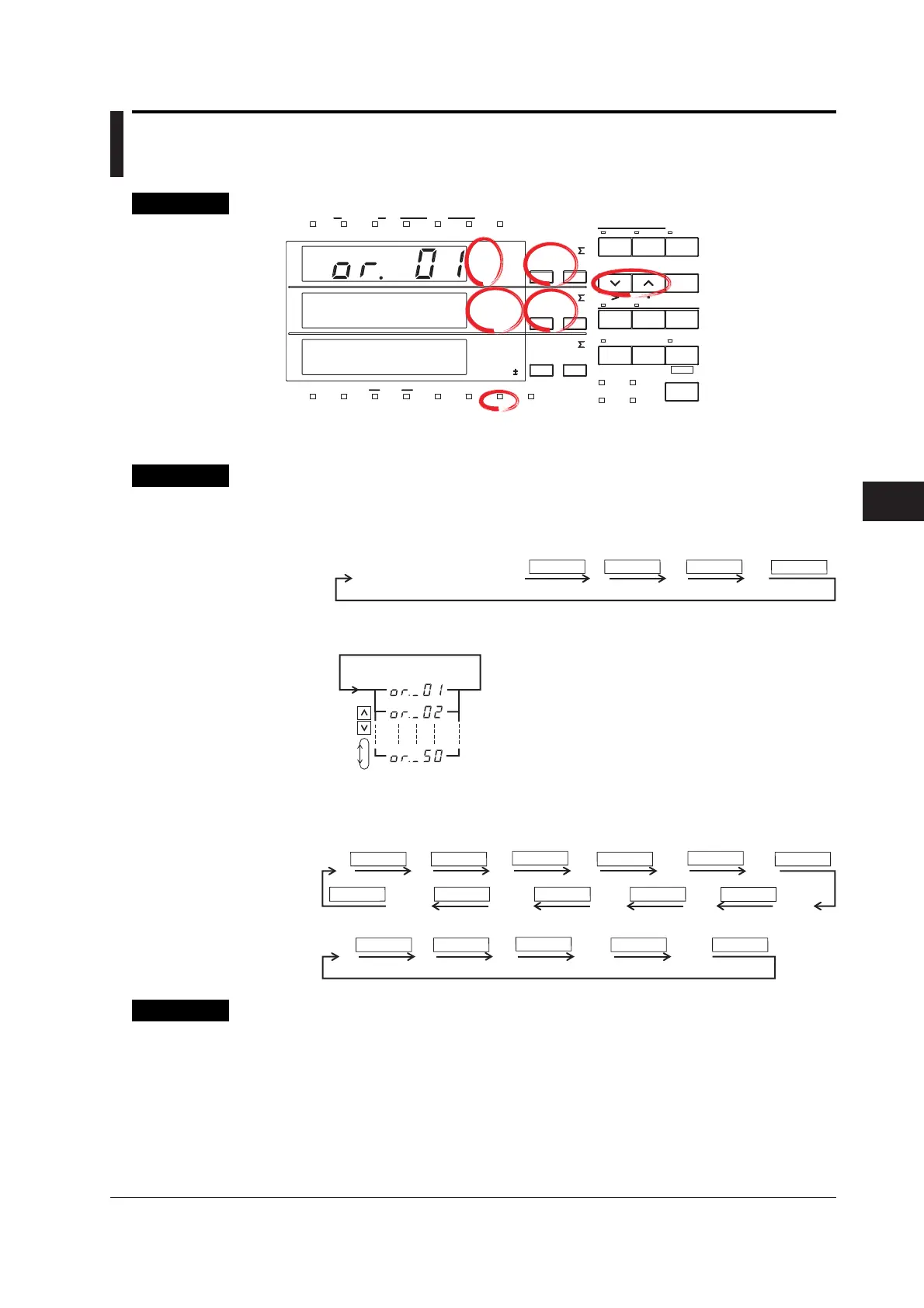
Setting the Harmonics Order
1. Light up the display function indicator of display A.
Display
A
Light up display function
FUNCTION FUNCTION FUNCTION
FUNCTION
2. Set the harmonics order.
(Display A)
Displaying the Measured Harmonic Values
Displays each measured value after having set the display function of either display B
or C.
FUNCTION
VA W PF
FUNCTION
FUNCTION
FUNCTION
FUNCTION
FUNCTION
V% A%
W%Vdeg A%
V%Adeg
FUNCTION FUNCTIONFUNCTIONFUNCTIONFUNCTION
Display
B
FUNCTION
VAWV Hz
FUNCTION
FUNCTION
FUNCTION FUNCTION
A Hz
Display
C
Explanation
Setting the Order of Harmonics
The maximum order for which analysis results can be displayed varies depending on
the frequency of the fundamental.
Example
• When the fundamental frequency is 50 Hz, up to 50 orders can be displayed;
• When the fundamental frequency is 400 Hz, up to 30 orders can be displayed.
When an order is set exceeding the maximum order, display B will change to the dot
display. Refer to Chapter 16 for more details on upper limits of analysis orders.

 Loading...


