S-8 IM 760401-01E
Selecting the Wiring System
<<For details, see section 3.10.>>
After wiring the circuit, select the wiring circuit. Select the wiring system to match the circuit
under measurement that is actually wired. When input element Σ is selected, the average
voltage or current of each input element that corresponds to the selected wiring system and
the sum of powers of each input element are displayed.
For the computing equation of the sum of powers, see section 16.3.
For the procedure of selecting input element Σ, see pages S-15 to S-17.
A
B
C
FUNCTION
ELEMENT
1
m
V
k
A
V
TIME
ar
deg
h
h
VA
MW
m
VPF
k
A
MW
m
VHz
k
A
MW
23
FUNCTION
ELEMENT
123
FUNCTION
ELEMENT
123
VOLTAG E
AUTO
MODE
CURRENT
AUTO
RANGE
MAX HOLD
TRIG
CAL
INTEGRATOR
INTEG SET
SHIFT
KEY LOCK
1P3W
3P3W
3P4W
3V3A
OUTPUT
HARMONICS
MEMORY
REMOTE
HOLD
ENTER
RESET
WIRING
START STOP
LOCAL
SETUP
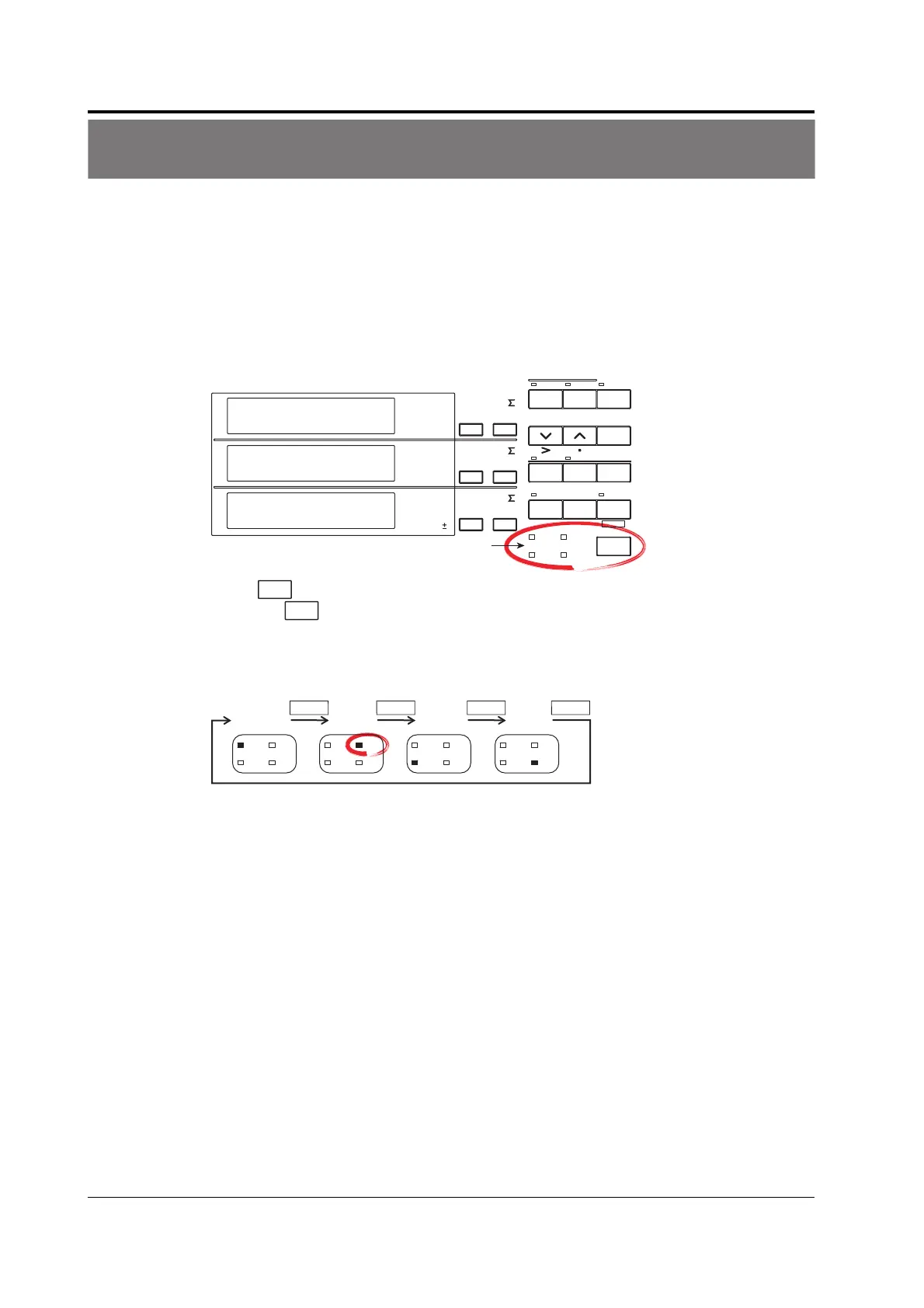
Wiring system indicator
%
Press
WIRING
to select wiring system 3P3W.
Each time
WIRING
is pressed, the wiring system indicator illuminates in the order shown in
the figure below. Since the example in this guide uses input element 1 and 3 of the
WT230 (760503, three-phase, four-wire model) with the wiring system of the secondary
side of the inverter set to three-phase, three-wire, wiring system 3P3W is selected.
WIRING WIRING WIRING WIRING
1P3W
3P3W
3P4W
3V3A
1P3W
3P3W
3P4W
3V3A
1P3W
3P3W
3P4W
3V3A
1P3W
3P3W
3P4W
3V3A
3P3W

 Loading...


