S-3
IM 760401-01E
Startup Guide
Below is a wiring example of a circuit used to measure the efficiency of an inverter using the
WT230 Digital Power Meter (760503, three-phase, four-wire model). To compute the
efficiency on the WT230 (760503, three-phase, four-wire model) when the primary side of
the inverter is a single-phase, two-wire system and the secondary side is a three-phase,
three-wire system, wiring must be furnished to input elements 1 and 3 using a three-phase,
three-wire system.
Inverter
Primary side
(Input)
Secondary side
(Output)
W2
W3
W1
Load
(Motor)
Power supplied by the source (= W2)
Power consumed by the load (= W1 + W3)
× 100(%)
Efficiency =
W2: Active power measured by input element 2 of the WT230
W1: Active power measured by input element 1 of the WT230
W3: Active power measured by input element 3 of the WT230
Wiring: Single-phase, two-wire
Wiring: Three-phase, three-wire
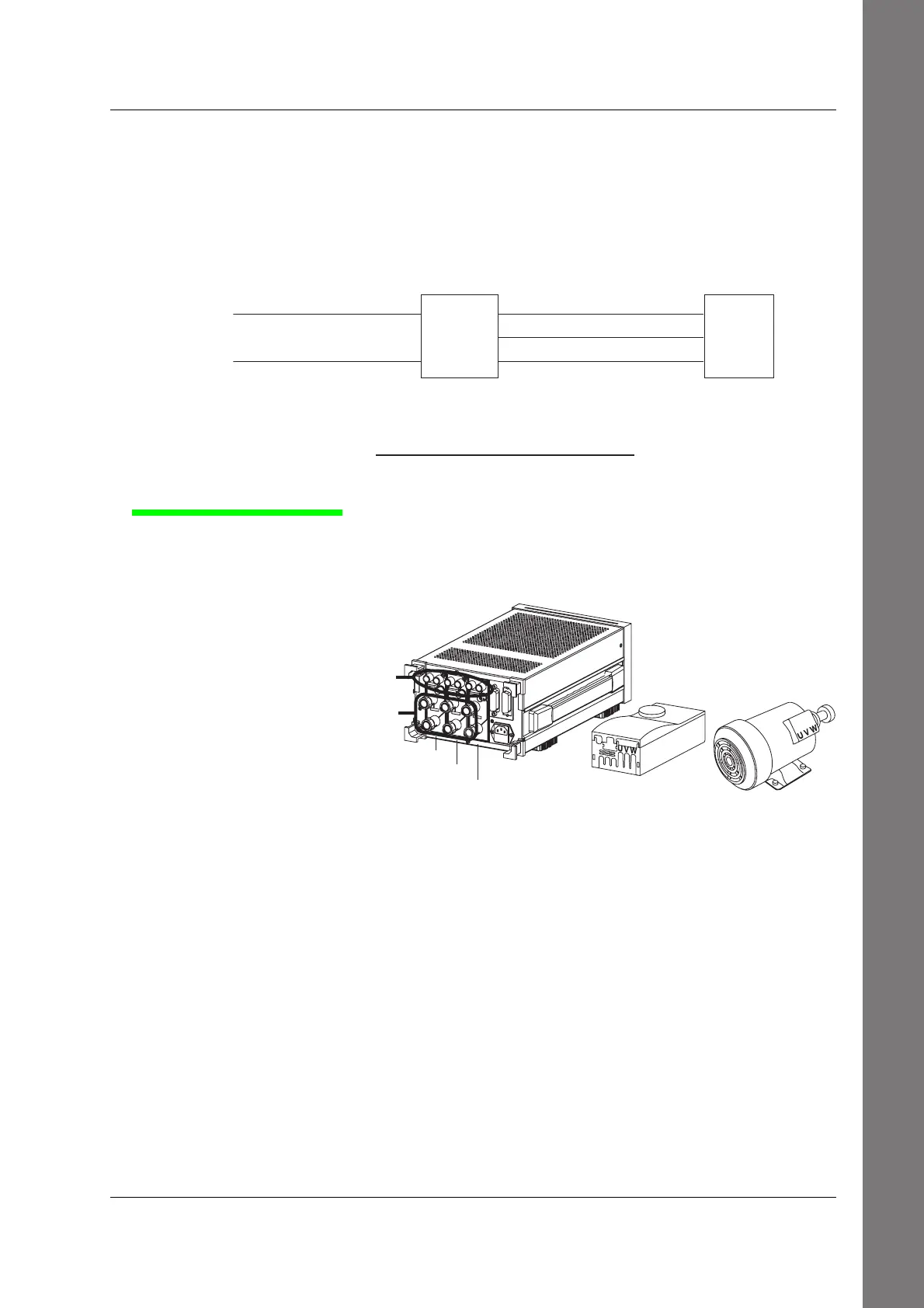
Installing the WT230
<<For details, see section 3.2.>>
1.
Install the WT230 (760503, three-phase, four-wire model).
Install the inverter to be measured and the motor also.
WT230
Inverter Motor
Input element 1
Input element 2
Input element 3
Voltage input terminal
Current input terminal
Wiring the Circuit

 Loading...


