S-5
IM 760401-01E
Startup Guide
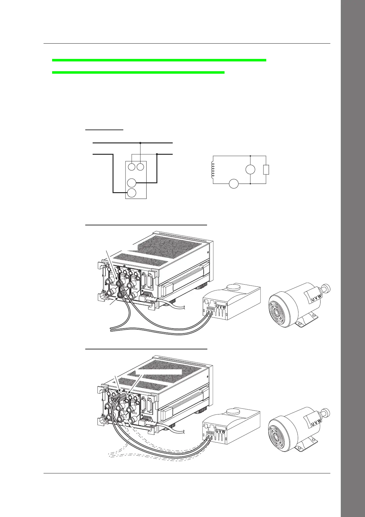
Wiring the Circuit on the Primary Side of the Inverter
(Wiring a Single-Phase, Two-Wire System)
<<For details, see section 3.7.>>
6.
Connect the voltage and current input terminals of input element 2 on the rear
panel of the WT230 (760503, three-phase, four-wire model) and the current
measurement circuit and voltage measurement circuit on the primary side of the
inverter.
Wiring Diagram
SOURCE
LOAD
C
±
Input terminal
(ELEMENT 2)
SOURCE
LOAD
(Inverter: primary side)
V2
A2
±
C
V
V
V: VOLTAGE terminal
C: CURRENT terminal
±
±
Wiring Example of a Current Measurement Circuit
WT230
Inverter Moter
TO SOURECE
±terminal
CURRENT terminal
Wiring Example of a Voltage Measurement Circuit
WT230
Inverter Moter
To SOURCE
VOLTAGE termonal
±terminal
Wiring the Circuit

 Loading...


