4-1
IM 760401-01E
Setting Measurement Conditions and Measurement Range
4
Chapter 4 Setting Measurement Conditions and Measurement Range
4.1 Selecting the Measurement Mode
Keys
CHECK RANGE
MODE
UPDATE
SCALING
AVG
LINE FREQ
STORE RECALL
HARMONICS
KEY LOCK
FILTER
A
B
C
VOLTAGE VOLTAGE
VOLTAGE
AUTO
MODE
CURRENT
AUTO
RANGE
MAX HOLD
TRIG
CAL
INTEGRATOR
INTEG SET
SHIFT
KEY LOCK
1P 3W
3P 3W
3P 4W
3V 3A
OUTPUT
HARMONICS
MEMORY
REMOTE
MEAN
CURRENT RMS
DC
FUNCTION
ELEMENT
MAX HOLD
HOLD
ENTER
RESET
WIRING
START STOP
LOCAL
SETUP
1
m
V
k
A
V
TIME
ar
deg
h
h
VA
MW
m
VPF
k
A
MW
m
VHz
k
A
MW
23
FUNCTION
ELEMENT
123
FUNCTION
ELEMENT
123
%
The explanation given in this section uses WT230 as an example. For the differences between
the WT210 and the WT230, see section 2.2, “Operation Keys and Functions/Element Display.”
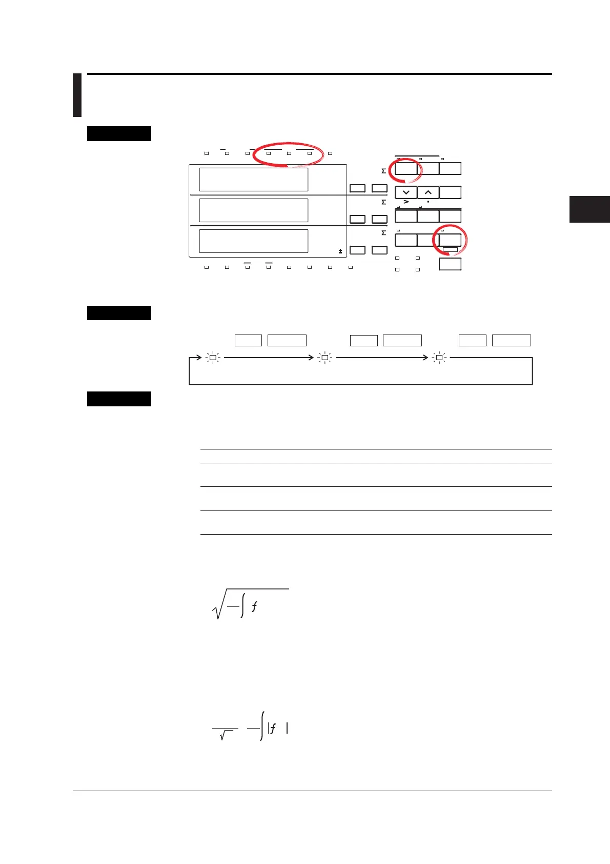
Procedure
RMS
VOLTAGE
MEAN
DC
MODE
SHIFT
MODE
VOLTAGE VOLTAGE VOLTAGE
SHIFT
MODE
SHIFT
Explanation
Measurement Mode
One of the following measurement modes can be selected for measurement of voltage
and current. The initial value is “RMS”.
Indicator Voltage Current
RMS Measures and displays true Measures and displays true RMS
RMS value value
VOLTAGE MEAN Displays rectified mean value Measures and displays
calibrated to the RMS value true RMS value
DC Displays DC value obtained by Displays DC value obtained by averaging
averaging the input signal the input signal
Theoretical Equations
• RMS
This mode is selected to display input voltage or current as a true RMS value.
T
1
T
0
(t)
2
dt
f (t): input signal
T: one period of the input signal
• VOLTAGE MEAN
This mode is selected to display input voltage or current as a rectified mean value
calibrated to the RMS value. Since a sine wave is used for calibration, the value
displayed will be the same as that obtained in RMS mode if a sine wave is
measured. The value displayed will be different from that obtained in RMS mode if
a distorted or DC waveform is measured.
T
1
(t)
dt
2
2
·
π
T
0
f (t): input signal
T: one period of the input signal
•DC
This mode is selected when the input voltage or current is DC. The input signal is
averaged and the result is displayed.

 Loading...


