x IM 760101-01E
Symbols Used on Pages Describing Operating Procedures
The following symbols are used to distinguish the contents of the explanations.
Keys
Indicates the keys and indicators related to the settings.
Procedure
The procedure is explained using a flow diagram. For the meaning
of each operation, see the example below. All procedures are
written with inexperienced users in mind; exp
erienced users may not need to carry out all the steps.
Example
1.
SHIFT
SETUP
OUTPUT
ENTER
3.
(Display C)
(Display C)
2.
ENTER
5.
4.
End of
setting
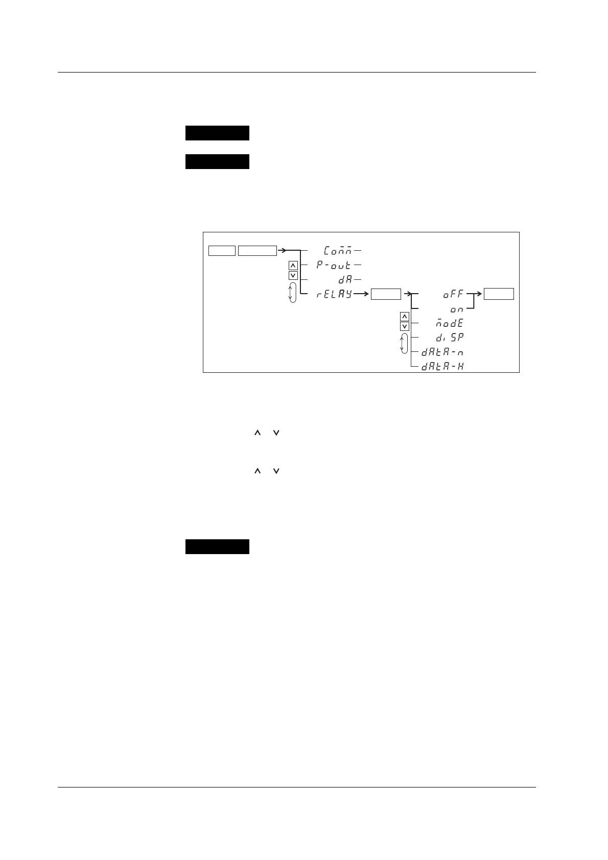
The flow diagram above indicates the following setup procedure.
You can set up the display that is blinking.
1. Press the SHIFT key to illuminate the SHIFT indicator and then press the
SETUP(OUTPUT) key.
The output setup menu appears on display C.
2. Press the or key to select rELAY.
The four selectable items appear repetitively by pressing either key.
3. Press the ENTER key to confirm the settings.
The setup menu corresponding to the function selected in step 2 appears on display C.
4. Press the or key to select oFF or on.
The six selectable items appear repetitively by pressing either key.
5. Press the ENTER key to confirm the settings.
When entering a sign or a value, an under bar blinks at the corresponding entry
digit if the digit is blank (space).
Explanation
This section describes the setup parameters and the limitations
regarding the procedures.
Conventions Used in This Manual

 Loading...


