10-9
IM 760401-01E
GP-IB Interface (Option)
10
Output Format of Harmonic Measurement Data
Data Format
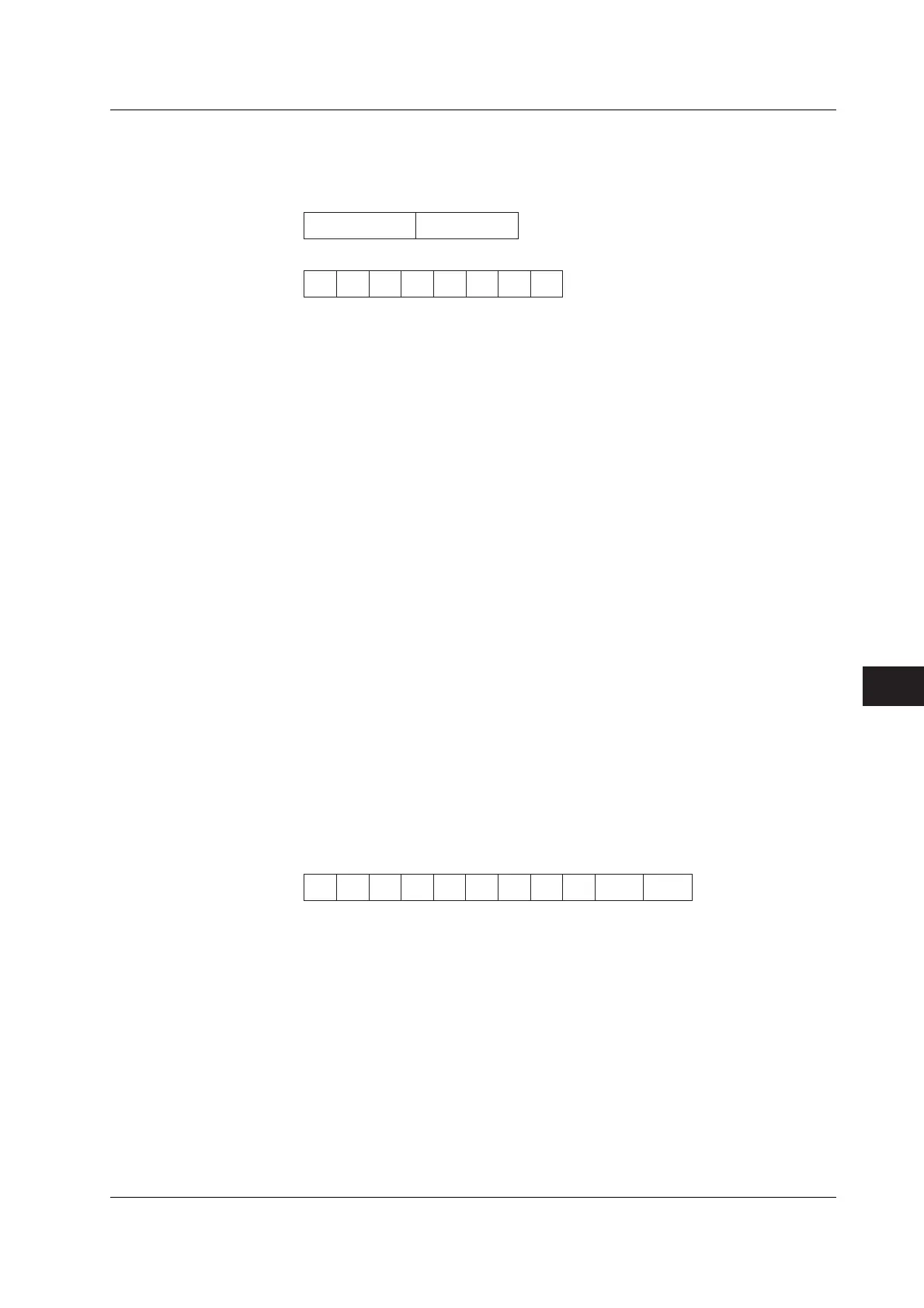
Harmonic measurement data consists of an 8-byte header and 11-byte data (total of
19 bytes).
Header (8 bytes) Data (11 bytes)
Header Section
h1 h2 h3 h4 h5 h6
h8h7
h1 to h3: data type
V__: voltage A__: Current W_: Active power
DEG: Phase angle between the 1st order voltage and 1st order current
DGV: Phase angle between the 1st order voltage and the 2nd to 50st order voltage
DGA: Phase angle between the 1st order current and the 2nd to 50st order current
PF_: Fundamental power factor (1st order)
HzV: Fundamental frequency of the voltage of the PLL source
HzA: Fundamental frequency of the current of the PLL source
THD: Harmonic distortion (either IEC or CSA)
CNT: Relative harmonic content
MEM: Data number in case of recalling
h4: Element
1: Element 1 2: Element 2 3: Element 3
h5: Data state
N: normal I: Overrange O: Computation overflow P: Peak overflow
E: No data
h6, h7: Order
01 to 50: Order of fundamental or higher harmonic (up to the maximum analysis
order).
“__” (space) will be assigned in case of frequency, harmonic distortion, power
factor or in case of all computed values of the 1st to 50th order.
h8: Indicates data lag/lead in case of DEG data type. In case of other data types, __
(space) will occur.
G: Lag D: Lead _: Not detectable
Data Section
d1 d2 d3 d4 d5 d6 d7 d8 d9 d10 d11
d1: polarity; __ (space) or – (minus)
d2 to d8: mantissa, floating-point number of the maximum six digits
• In case of harmonic distortion and relative harmonic content
d9: % d10 to d11: __ (space)
• In other cases
d9 to d11: exponent E–3 → m, E+0, E+3 → k, E+6 → M
10.4 Output Measured/Computed Data, Setup Parameters, and Error Codes

 Loading...


