3-12 IM 760401-01E
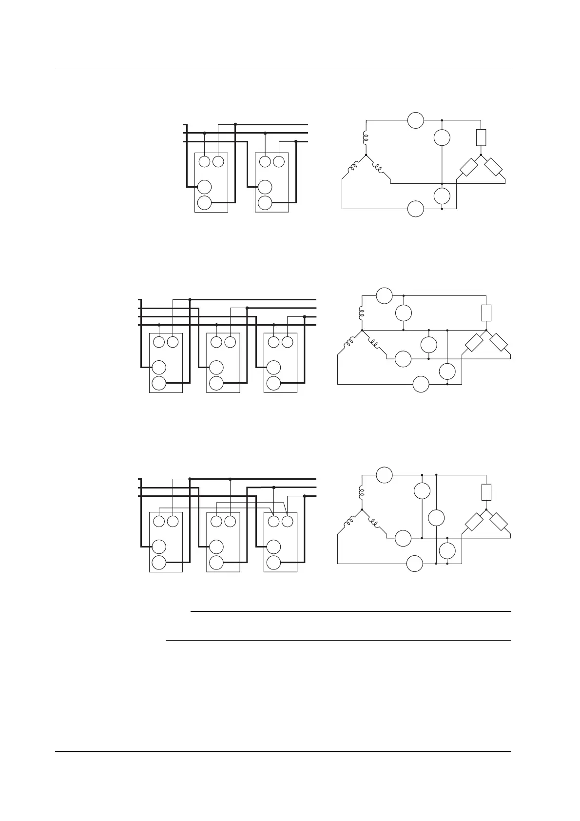
Wiring example of a three-phase, three-wire system (3P3W) ... Can be applied to
models 760502, and 760503.
Source
Load
A1
±C
±
A3
±
C
V1
±
V
V3
V
U(R)
V(S)
W(T)
Source Load
C
±
±
Input terminal
(Element 1)
V
V : VOLTAGE terminal
C : CURRENT terminal
U(R)
V(S)
W(T)
C
±
±
Input terminal
(Element 3)
V
Wiring example of a three-phase, four-wire system (3P4W) ... Can be applied to model
760503.
Source
Load
A1
±C
±
A3
±
C
V1
±
V
V3
V
U(R)
N
V(S)
W(T)
Source
C
±
±
Input terminal
(Elemnt 1)
V
V : VOLTAGE terminal
C : CURRENT terminal
U(R)
V(S)
W(T)
N
C
±
±
Input terminal
(Element 2)
V
load
C
±
±
Input terminal
(Element 3)
V
V2
±
V
A2
±C
Wiring example of a three-voltage, three-current system (3V3A) ... Can be applied to
model 760503.
Source
Load
A1
±
C
±
A3
±
C
V1
±
V
V3
V
U(R)
N
V(S)
W(T)
Source
C
±
±
Input terminal
(Element 1)
V
V : VOLTAGE terminal
C : CURRENT terminal
U(R)
V(S)
W(T)
C
±
±
Input terminal
(Element 2)
V
Load
C
±
±
Input terminal
(Element 3)
V
V2
±
V
A2
±
C
Note
For the relationship between the wiring systems and the method of determining the measured
values or computed values, see page 16-6.
3.7 Directly Wiring the Circuit under Measurement

 Loading...


