IM 01C50B01-01E
2-7
2. NOTES ON HANDLING
Note 4. Maintenance and Repair
• The instrument modification or parts replacement by
other than authorized representative of Yokogawa
Electric Corporation is prohibited and will void
Type of Protection “n” Certification.
Temperature
Transmitter
Suppry
Power Supply
Hazardous
Location
(Zone 2 only)
Nonhazardou
Location
+
–
+
–
[Installation Diagram]
F0212.EPS
Ratings of the Power Supply are as follows:
Maximum Voltage: 30 V
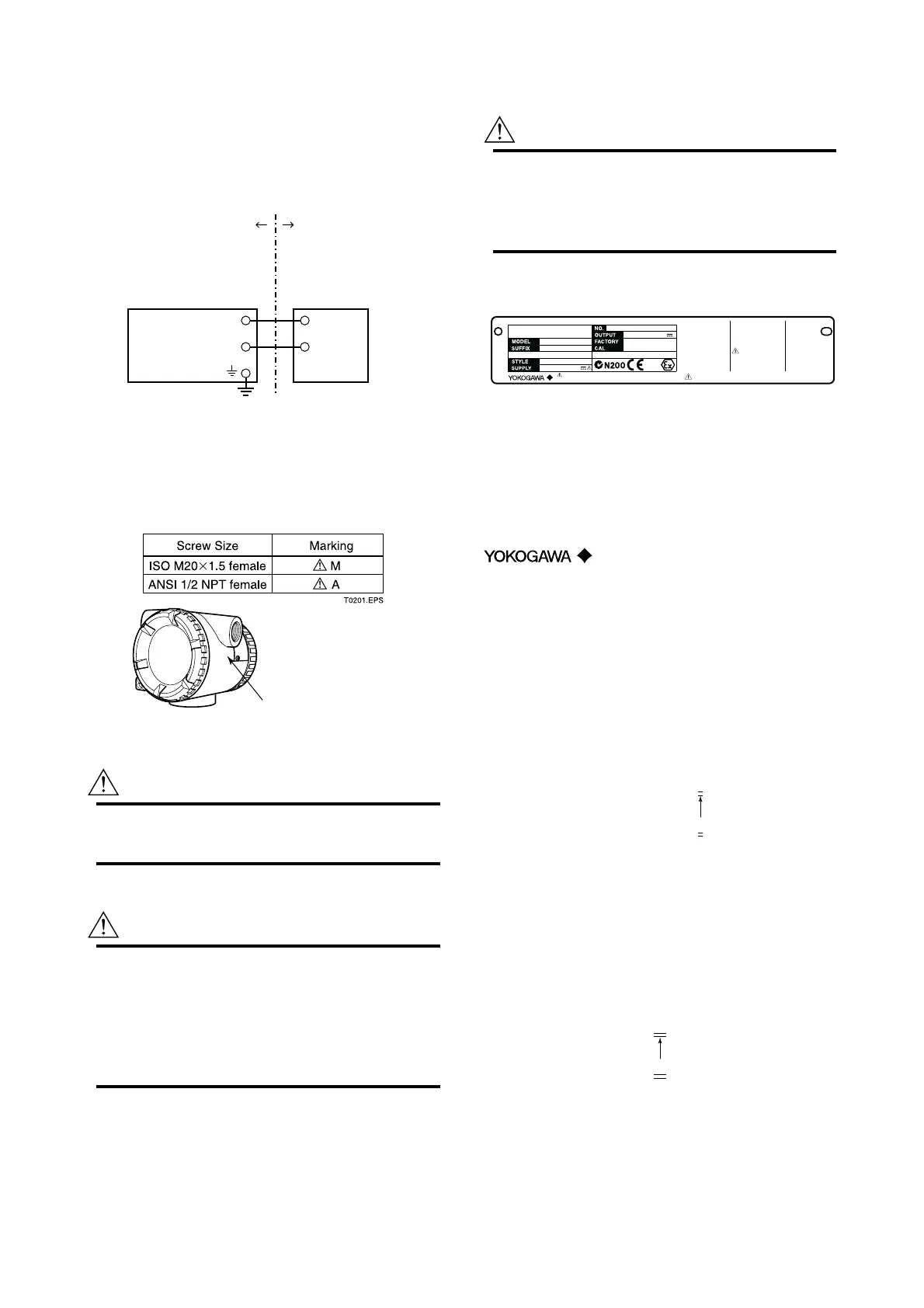
(2) Electrical Connection
The type of electrical connection is stamped near
the electrical connection port according to the
following marking.
F0200.EPS
Location of the marking
(3) Installation
WARNING
All wiring shall comply with local installation
requirement and local electrical code.
(4) Operation
WARNING
• OPEN CIRCUIT BEFORE REMOVING
COVER. INSTALL IN ACCORDANCE WITH
THIS USER’S MANUAL
• Take care not to generate mechanical sparking
when access to the instrument and peripheral
devices in hazardous locations.
(5) Maintenance and Repair
WARNING
The instrument modification or parts replacement
by other than authorized Representative of
Yokogawa Electric Corporation is prohibited and
will void the certification.
(6) Name Plate
F0298.EPS
Name plate for type n protection
TEMPERATURE
TRANSMITTER
YTA
TOKYO 180-8750 JAPAN
4
⫺
20 mA DC
0344
10.5⫺30 (42) V DC
:Refer to USER’S MANUAL.
AFTER DE-ENERGIZING, DELAY
5 MINUTES BEFORE OPENING.
WHEN THE AMBIENT TEMP.⭌70⬚C,
USE THE HEAT-RESISTING
CABLES⭌90⬚C.
WARNING
of protection. When II 3G is selected, cross out 0344.
No. KEMA 02ATEX1026 X
EEx ia IIC T5
Tamb -40 TO 50⬚C
EEx ia IIC T4
Tamb -40 TO 70⬚C
ENCLOSURE: IP67
No. KEMA 02ATEX2155
EEx d IIC T6
Tamb -40 TO 75⬚C
EEx d IIC T5
Tamb -40 TO 80⬚C
ENCLOSURE: IP67
EEx nL IIC T5
Tamb -40 TO 50⬚C
EEx nL IIC T4
Tamb -40 TO 70⬚C
ENCLOSURE: IP67
SUPPLY INPUT
Ui=30V
Ci=20nF, Li=660H
SENSOR OUTPUT
Uo=8.6V, Io=30mA
Po=7 0mW, Co=3F
Lo=20mH
II
1G
2GII II 3G
Cross out unnecessary marking other than the selected type
SUPPLY INPUT
Ui=30V, Ii=165mA, Pi=900mV
Ci=20nF, Li=660H
SENSOR OUTPUT
Uo=8.6V, Io=30mA, Po=70mW
Co=3F, Lo=20mH
MODEL: Specified model code.
SUFFIX: Specified suffix code.
STYLE: Style code.
SUPPLY: Supply voltage.
NO.: Serial number and year of production
*1
.
OUTPUT: Output signal.
FACTORY CAL: Specified calibration range.
TOKYO 180-8750 JAPAN:
The manufacturer name and the
address
*2
.
*1: (a) The production year for the serial number
starting with other than “S.”
The third figure from the last shows the last one
figure of the year of production. For example, the
production year of the product engraved in “NO.”
column on the name plate as follows is 2001.
The year 2001
12A819857 132
(b) The production year for the serial number
starting with “S.”
The third and fourth figures from the left show the
last two figures of the year of production. For
example, the production year of the product
engraved in “NO.” column on the name plate as
follows is 2001.
The year 2001
S201D0229335
*2: “180-8750” is a zip code which represents the
following address.
2-9-32 Nakacho, Musashino-shi, Tokyo Japan

 Loading...