IM 01C50B01-01E
5-2
5. WIRING
CAUTION
When wiring, pay attention not to damage the
cable and cores. All the cores of the cable must
have the sufficient insulation around them.
F0504.EPS
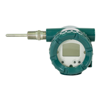
a. Cable connection to thermometer resistor(RTD),
3-wire
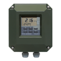
b. Power supply cable connection
STEP 1
(1)
STEP 2
(2)
Figure 5.4 Terminal Connection Pro cedure
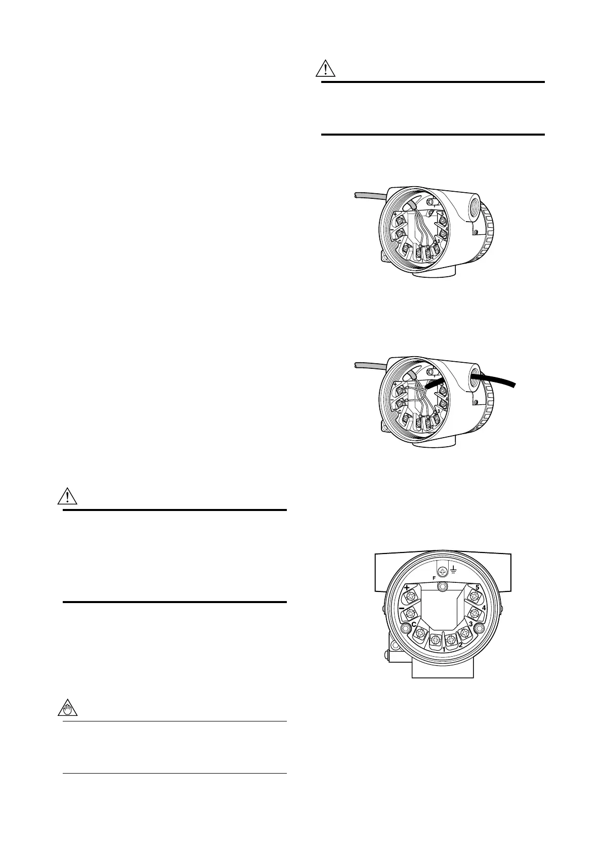
䊏 The temperature sensor is to be connected
as shown in Figures 5.6 and 5.7.
F0505.EPS
Figure 5.5 Terminal diagram
5.3 Cable Selection
5.3.1 Input signal Cable Selection
A dedicated cable is used for connection between the
temperature sensor and the temperature transmitter.
When a thermocouple is used as the temperature
sensor, a compensation wire must be used that it
appropriate for the type of thermocouple (refer to
compensating cables for JIS C 1610/IEC584-3 thermo-
couples). When a resistance temperature sensor (RTD)
is used as the temperature sensor, 2-core/3-core/4-core
cable must be used (refer to resistance thermometer
sensor JIS C 1604/IEC751). The terminal of the
dedicated cable is a 4 mm screw.
5.3.2 Output Signal Cable Selection
• With regard to the type of wire to be used for
wiring, use twisted wires or cables with perfor-
mance equivalent of 600V vinyl insulated cable
(JIS C3307).
• For wiring in areas susceptible to electrical noise,
use shielded wires.
• For wiring in high or low temperature areas, use
wires or cables suitable for such temperatures.
• For use in an atmosphere where harmful gases or
liquids, oil, or solvents are present, use wires or
cables made of materials resistant to those sub-
stances.
• It is recommended that a self-sealing terminal with
insulation sleeve (4-mm screw) be used for lead
wire ends.
WARNING
If the YTA is JIS flameproof and the ambient
temperature is 50°C or more, use an external
cable having a maximum allowable heat resis-
tance of at least 70°C in consideration of the
instrument’s generation of heat or the cable’s
self-heating.
5.4 Cable and Terminal Connec-
tions
5.4.1 Input Terminal Connections
NOTE
It is recommended that the terminals be con-
nected in the order of input terminal (1) and
output terminal (2).

 Loading...