IM 01C50B01-01E
6-3
6. MAINTENANCE
6.3.1 Replacement of Built-in Indicator
䊏 Removal of built-in indicator
1. Remove the cover.
2. Loosen two mounting screws while using your hand
to support the built-in indicator.
3. Remove the LCD assembly from the CPU assem-
bly. At this time, straighten and pull the LCD
assembly forward so that the connector connecting
the CPU assembly and the LCD assembly is not
damaged.
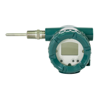
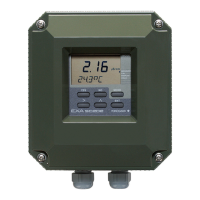
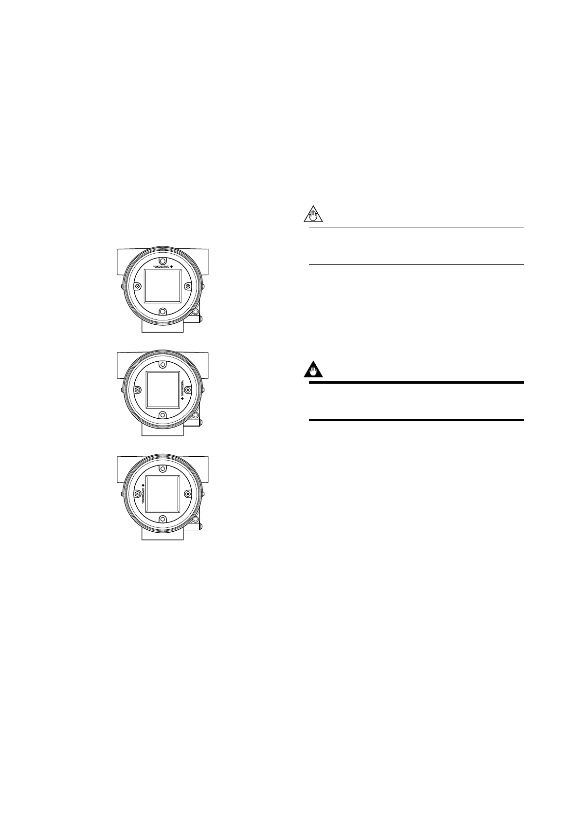
䊏 Mounting the built-in indicator
Integral Indicator can be installed in the following
three directions.
F0603.EPS
Figure 6.4 Installation Direction of Indicator
1. Place the LCD assembly in desired direction over
the CPU assembly.
2. Align the mounting hole of the LCD assembly with
the stud bolt hole, and carefully insert the indicator
into the connector in a straight manner so that the
connector is not damaged.
3. Tighten the two mounting screws that secure the
indicator.
4. Install the cover.
6.3.2 Replacement of CPU Assembly
䊏 Removal of CPU assembly
1. Remove the cover.
2. Use a Phillips screwdriver to loosen the two screws.
3. For a CPU assembly with a built-in indicator,
remove it as described in Section 6.3.1. Next loosen
the two stud bolts.
4. Pull the CPU assembly directly toward you.
5. Remove the cable (with a brown connector attached
at the head).
Use care not to apply excessive force to the
CPU assembly during removal.
䊏 Mounting the CPU assembly
1. Connect the cable with the CPU assembly.
2. Align the pin on the base board with the connector
(black) of the CPU assembly, and insert the CPU
assembly straight into the board.
IMPORTANT
Use care not to pinch the cable under the cover,
and fully insert the cable into the case.
3. Loosen the two screws. If the unit includes a built-
in indicator, install it as described in Section 6.3.1.
4. Mount the cover.

 Loading...