IM 01C50B01-01E
6-4
6. MAINTENANCE
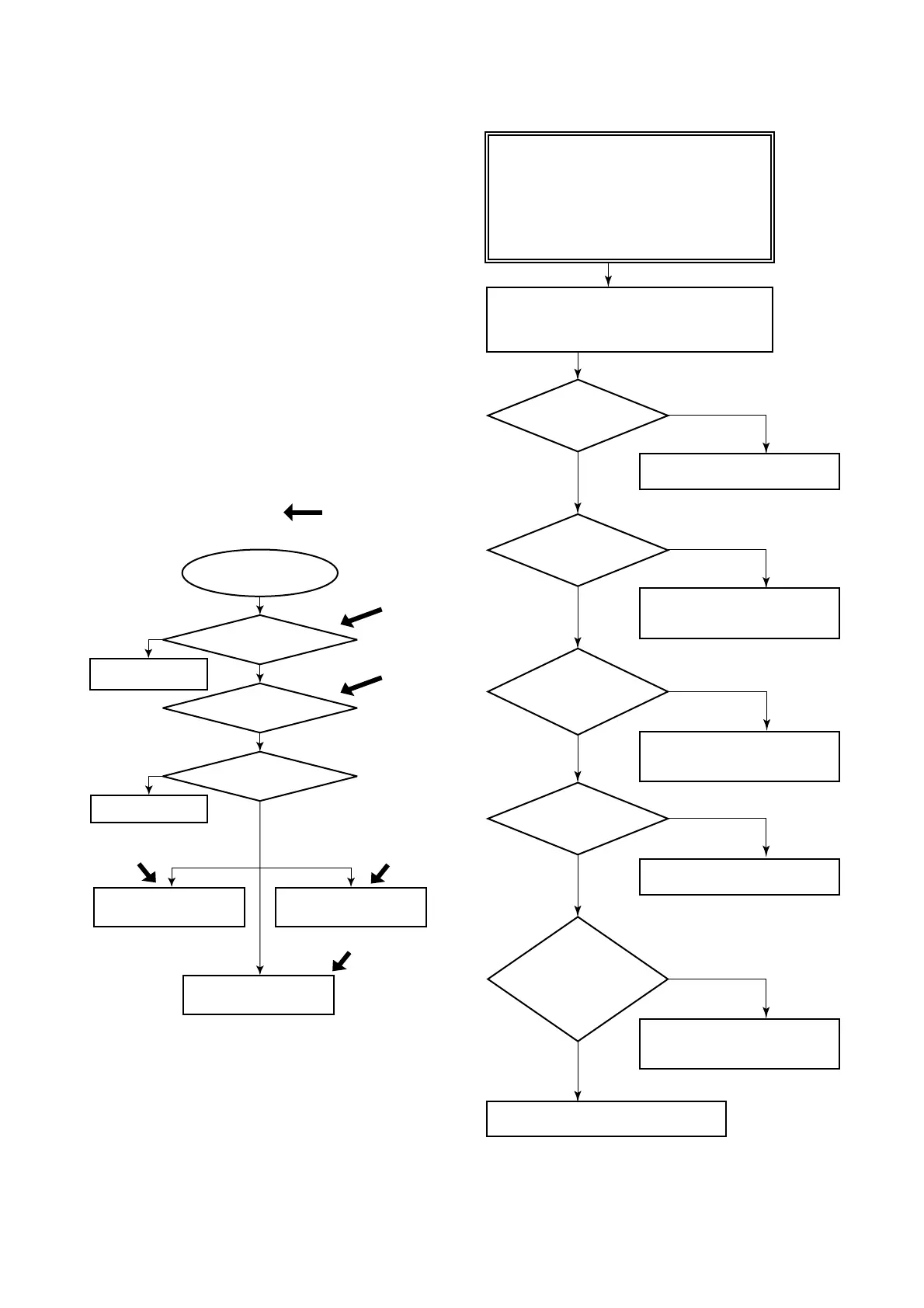
6.4 Troubleshooting
When the measured value is found abnormal, follow
the troubleshooting flowchart below. If the complex
nature of the trouble means that the cause cannot be
identified using the following flowchart, refer the
matter to our service personnel.
6.4.1 Basic Troubleshooting Flow
When the process measurement is found to be abnor-
mal, it is necessary to determine whether the input
temperature is out of range, the sensor has failed or
being damaged, or the unit has been improperly wired.
If it is suspected that the measurement system is the
source of the problem, use the flowchart to identify the
affected area and determine how to proceed.
In these troubleshooting steps, the self diagnostic
function provides helpful solutions to the problem,
refer to the instructions in Section 6.5 for details.
YES
YES
NO
NO
F0604.EPS
Measured value
is found faulty
Error in process
variable?
Faulty
area in measurement
system
Receiver error
Operating requirements:
check, study, correction
Check the transmitter
Environmental condition:
check, study, correction
Environmental condition
Operating requirements
Error in measurement
system
Transmitter
Inspect receiver
Inspect the process
:Part supported
by self-diagnosis
Figure 6.5 Basic Flow and Self-diagnosis
6.4.2 Example of Troubleshooting Flow
F0605.EPS
YES
NO
NO
YES
NO
YES
NO
NO
YES
YES
Was a faulty
area found with self-
diagnosis?
Is the polarity
of the power supply
correct?
Are the power
supply voltage and load
resistance correct?
Is the sensor
correctly connected?
Is there a
disconnection in the loop?
Do the loop numbers
correspond to the
counterpart?
The following phenomena indicate that this
instrument may be out of operation.
[Example]
• No output signal is delivered.
• Process variable changes but the output
signal remains unchanged.
• The assessed value of the process variable
and the output are not coincident.
Refer to our service personnel for details.
• If a built-in indicator is attached, check the
display of the error code.
• Connect a hand-held terminal and check
self-diagnosis.
Refer to the error message list and
check for recovery measures.
Check the polarity between the
power supply and terminal box and
correct it.
Refer to Section 5.2 and set
the specified voltage and load
resistance.
Check the sensor connection and
correct it.
Check for disconnection or faulty
wiring and take corrective
measures.
Figure 6.6 Example of Troubleshooting Flow

 Loading...