IM 01C50B01-01E
5-1
5. WIRING
5. WIRING
5.1 Notes on Wiring
IMPORTANT
• Apply a waterproofing sealant to the
threads of the connection port. (It is recom-
mended that you use non-hardening sealant
made of silicon resin for waterproofing.)
• Lay wiring as far away as possible from
electrical noise sources such as large trans-
formers, motors and power supplies.
• Remove the wiring connection dust-caps
before wiring.
• To prevent electrical noise, the signal cable
and the power cable must not be housed in
the same conduit.
• The terminal box cover is locked by an Allen
head bolt (a shrouding bolt) on CENELEC,
SAA and JIS flameproof type transmitters.
When the shrouding bolt is driven clockwise
by an Allen wrench, it is going in and cover
lock is released, and then the cove can be
opened by hands. See Subsection 6.3
“Disassembly and Reassembly” for details.
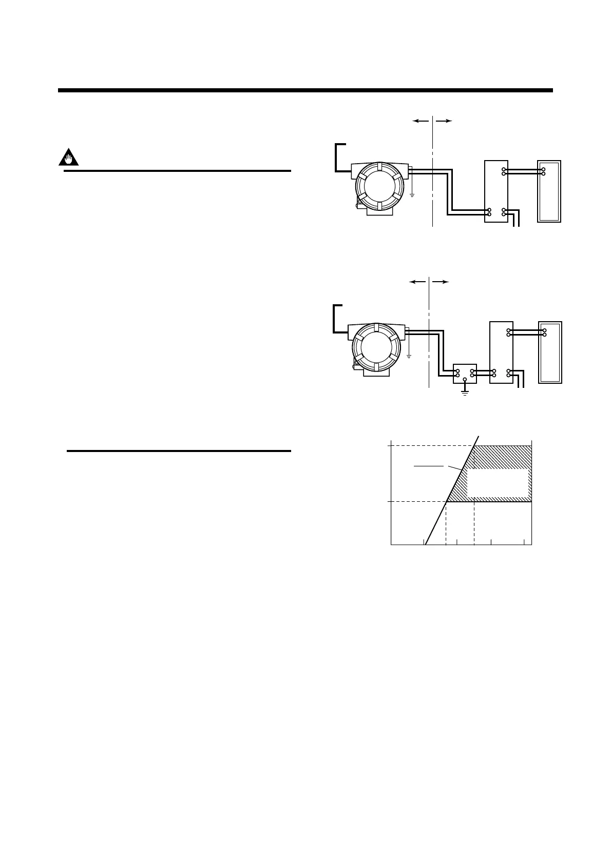
5.2 Loop Construction
The YTA is a two-wire temperature transmitter that
uses the output power supply wiring and signal wiring
alternately.
The transmission loop requires DC power. Connect the
transmitter with the distributor as shown in Figure 5.1
or Figure 5.2.
For the transmission loop, the load resistance of the
distributor or other instrument to be installed in the
loop and the lead wire must be within the range shown
in Figure 5.3.
For details of communication requirements, refer to the
additional reference materials, IM 01C50T03-01E “YTA
Series BRAIN Communication”, and IM 01C50T01-01E
“YTA Series HART Communication”.
F0501.EPS
<Hazardous location> <Nonhazardous location>
+
Output signal
–
Distributor
(power supply unit)
Receiver
Input signal
(thermocouple,
RTD, mV, etc.)
Figure 5.1 Loop Construction (for General-use Type and
Flameproof Type)
F0502.EPS
<Hazardous location> <Nonhazardous location>
+
Output signal
–
Distributor
(power supply unit)
Receiver
Safety
barrier
Input signal
(thermocouple,
RTD, mV, etc.)
Figure 5.2 Loop Construction (for Intrinsically Safe
Type)
600
250
10.5 16.4 24.7 42
Power supply voltage E (V DC)
R=
0.0236
E–10.5
F0503.EPS
External
load
resistance
R
(⍀)
Communication
applicable range
BRAIN and HART
Figure 5.3 Relation between Power Supply Voltage and
Load Resistance
Note: For intrinsic safe explosion-proof type units, the internal
resistance of the safety barrier is also included in the load
resistance.

 Loading...