IM 01C50B01-01E
2-9
2. NOTES ON HANDLING
c) IEC (KEMA) Type of Protection “n”
Caution for IEC (KEMA) Type of Protection “n”
Note 1. Model YTA110/KU1, YTA310/KU1 and
YTA320/KU1 ditemperature transmitters
for potentially explosive atmospheres:
• Type of Protection and Marking Code: Ex nC IIC
T5, T4
• Temperature Class: T5, T4
• Ambient Temperature: –40 to 50°C for T5, –40 to
70°C for T4
• Enclosure: IP67
Note 2. Electrical Data
Ui = 30 V Ii = 150 mA
(terminals + and –)
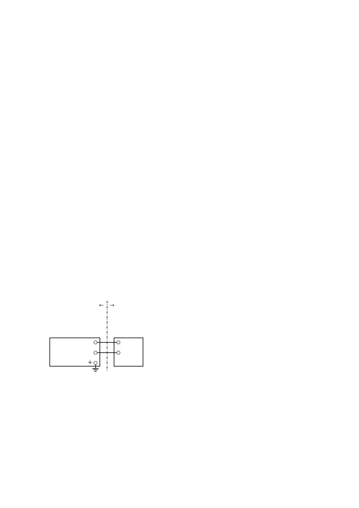
Note 3. Installation
•All wiring shall comply with local installation
requirements. (refer to the installation diagram)
Note 4. Operation
• Keep strictly the “WARNING” on the label on the
transmitter.
WARNING: WAIT 5 MIN. AFTER POWER-
DISCONNECTION, BEFORE
OPENING THE ENCLOSURE.
WHEN THE AMBIENT TEMP. ⭌
70⬚C, USE THE HEATRESIST-
ING CABLES OF HIGHER
THAN 90⬚C
Note 5. Maintenance and Repair
• The instrument modification or parts replacement by
other than authorized representative of Yokogawa
Electric Corporation is prohibited and will void
KEMA Type of Protection “n” Certification.
Temperature
Transmitter
Suppry
Power Supply
Hazardous
Location
(Zone 2 only)
Nonhazardou
Location
+
–
+
–
[Installation Diagram]
F0212.EPS
Ratings of the Power Supply are as follows:
Maximum Voltage: 30 V
Maximum Current: 150 mA
2.7.4 FM Certification
a) FM Intrinsically Safe Type
Caution for FM Intrinsically safe type.
Note 1. Model YTA /FU1 temperature transmitter
is applicable for use in hazardous
locations
• Intrinsically Safe for Class I, Division 1, Groups A,
B, C & D.
Class II, Division 1, Groups E, F & G and Class III,
Division 1 Hazardous Locations.
• Outdoor hazardous locations, NEMA 4X.
• Temperature Class: T4
• Ambient temperature: –40 to 60°C
Note 2. Entity Parameters of the temperature
transmitter:
• Supply Circuit (+ and -) •Sensor Circuit ( 1 to 5 )
Vmax : 30 V Voc/Vt : 9 V
Imax : 165 mA Isc/It : 40 mA
Pmax : 0.9 W Ca : 1 µF
Ci : 18 nF La : 10 mH
Li : 730 µH
• For the sensor input circuitry, these entity parameters
must be taken into account when installed.
• Installation Requirements between temperature
transmitter and safety barrier:
Voc Vmax, Isc Imax, Ca Ci + Ccable, La
Li + Lcable
Voc , Isc, Ca and La are parameters of the safety
barrier.
Note 3. Installation
• The safety barrier must be FM approved.
• Input voltage of the safety barrier must be less than
250 Vrms/Vdc.
•Installation should be in accordance with ANSI/ISA
RP12.6 “Installation of Intrinsically Safe Systems
for Hazardous (Classified) Locations” and the
National Electric Code (ANSI/NFPA 70).
• Intrinsically safe sensor must be FMRC Approved or
be simple apparatus (a device which will neither
generate nor store more than 1.2 V, 0.1 A, 25 mW
or 20 µJ, ex. switches, thermocouples, LED’s or
RTD’s).
• Dust-tight conduit seal must be used when installed
in a Class II and III environments.
Note 4. Maintenance and Repair
• The instrument modification or parts replacement by
other than authorized representative of Yokogawa
Electric Corporation is prohibited and will void
Factory Mutual Intrinsically safe and Nonincendive
Approval.

 Loading...