IM 01C50B01-01E
2-12
2. NOTES ON HANDLING
[Output parameters (terminals 1 to 5)]
Maximum Output Voltage(Uo) = 8.6 V
Maximum Output Current(Io) = 30 mA
Maximum Output Power(Po) = 62 mW
Maximum External Capacitance = 1 µF
Maximum External Inductance = 20 mH
Maximum External Connected L/R = 0.5mH/⍀
Note 3. Installation
•All wiring shall comply with Australian Standards.
• The input and output cables are to be installed either
as seperate cables or as seperate screened circuits.
• Certified IP66/67 glands or plugs must be used on
the enclosure cable entries.
Note 4. Maintenance and Repair
•The instrument modification or parts replacement by other
than authorized representative of Yokogawa Electric
Corporation is prohibited and will void SAA Certification.
Transmitter
Transmitter
Supply
Safety Barrier
*1
Hazardous Location
(Zone 0)
Nonhazardous Location
+
–
+
–
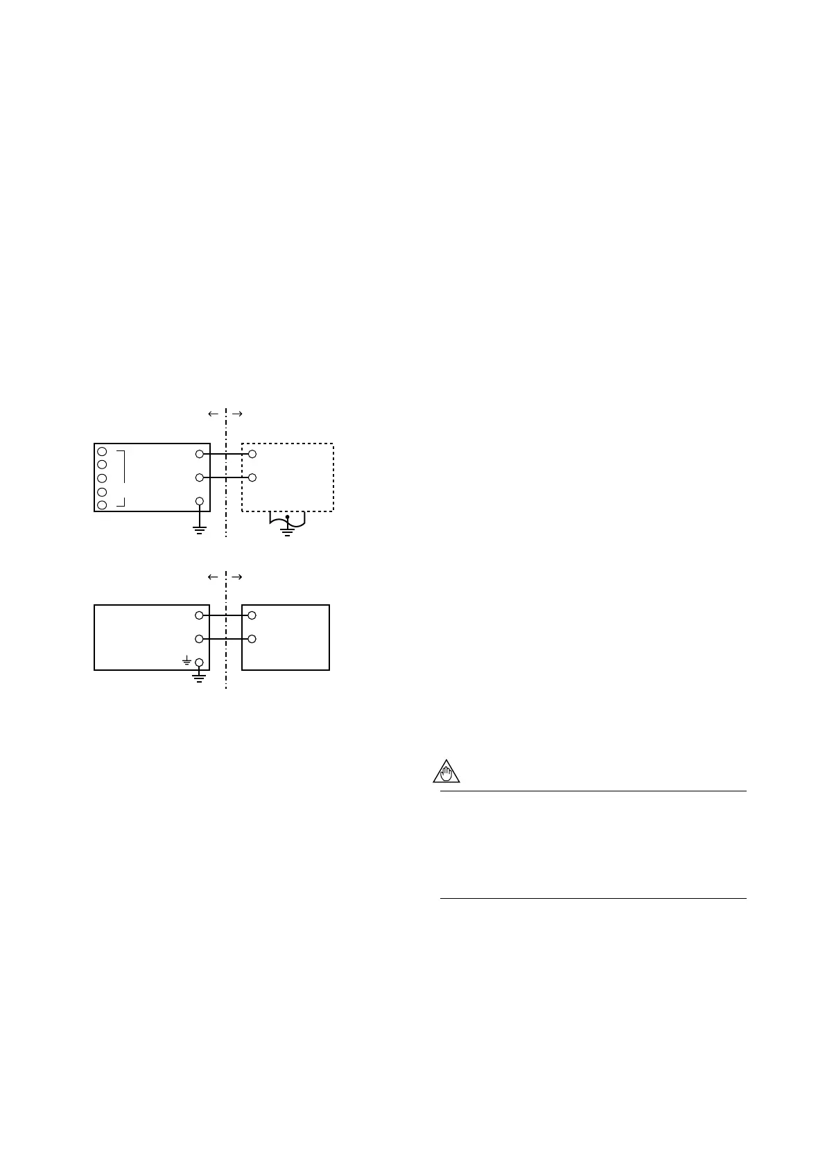
[Installation Diagram for intrinsically safe type]
F2013.EPS
Sensor
1
2
3
4
5
Nonhazardous Location
Suppry Power Supply
+
–
+
–
[ Installation Diagram for Type n ]
Hazardous Location
(Zone 2)
+
–
+
–
*1: In any safety barriers used the output current must be limited by
a resistor “R” such that Imaxout-Uz/R.
b) SAA Flameproof Type
Caution for SAA Flameproof Type
Note 1. Model YTA110/SU1, YTA310/SU1 and
YTA320/SU1 temperature transmitters for
potentially explosive atmospheres:
• Type of Protection and Marking Code:
Ex d IIC T6(Tamb 75°C) IP66/67 Zone 1
• Ambient Temperature: –40 to 75°C
Note 2.Electrical Data
• Supply voltage: 42 V dc max.
• Output signal: 4 to 20 mA
Note 3. Installation
•All wiring shall comply with Australian Standards.
•The cable entry devices shall be of a certified
flameproof type, suitable for the conditions of use.
Note 4. Operation
• Keep strictly the “WARNING” on the label on the
transmitter.
WARNING: WAIT 5 MIN. AFTER POWER-
DISCONNECTION, BEFORE
OPENING THE ENCLOSURE.
WHEN THE AMBIENT TEMP.
⭌ 70⬚C, USE THE HEATRESIST-
ING CABLES OF HIGHER THAN
90⬚C
• Take care not to generate mechanical spark when
access to the instrument and peripheral devices in
hazardous location.
Note 5. Maintenance and Repair
• The instrument modification or parts replacement by
other than authorized representative of Yokogawa
Electric Corporation is prohibited and will void SAA
Certification.
2.8 EMC Conformity Standards
EN61326, AS/NZS 2064
YOKOGAWA recommends customer to apply
the Metal Conduit Wiring or to use the twisted
pair Shield Cable for signal wiring to conform the
requirement of EMC Regulation, when customer
installs the YTA Series Transmitters to the plant.

 Loading...