IM 01C50B01-01E
7-5
7. STANDARD SPECIFICATIONS
Factory setting (䉫)
T0705.EPS
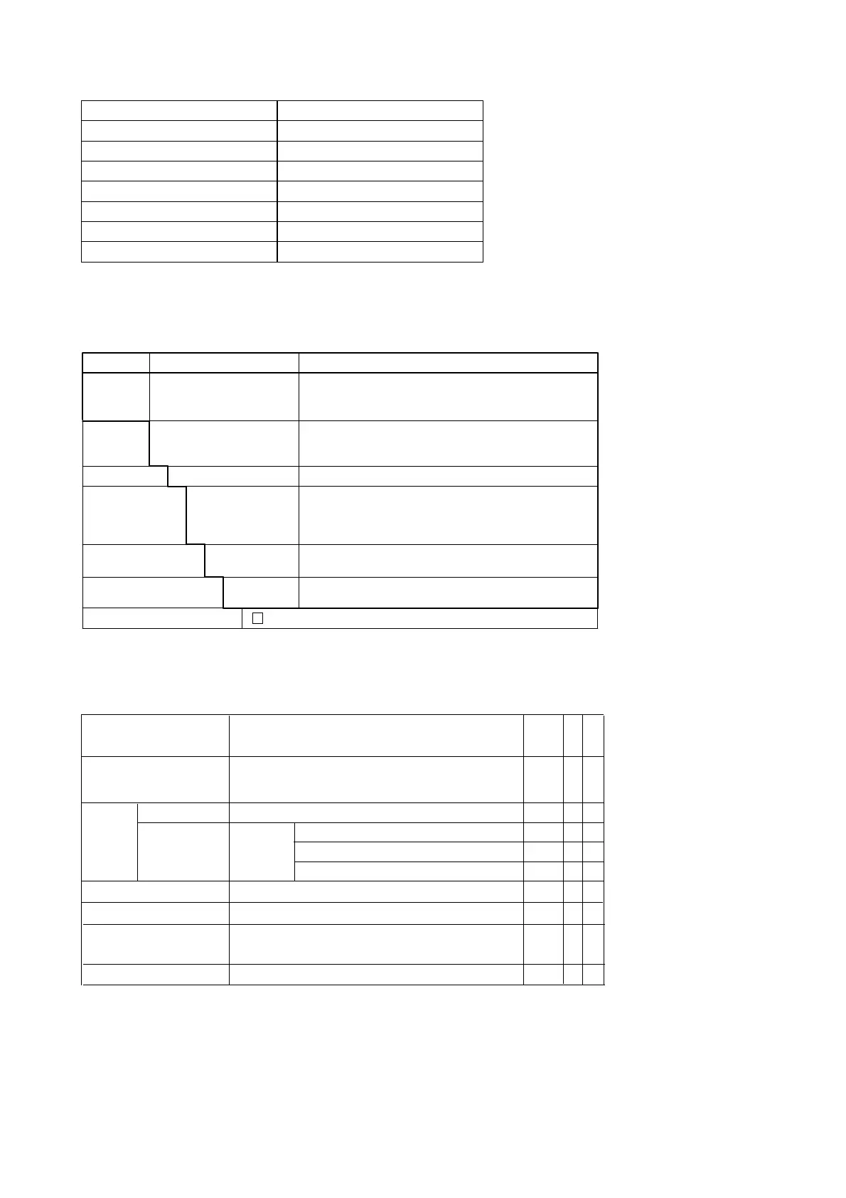
Tag No.
Input sensor type
Lower bound of calibration range
Upper bound of calibration range
Unit of calibration range
Damping constant
Sensor burnout
Output when transmitter fails
Left blank if not specified in order
“Pt100, 3-wire” if not specified in order
“0” if not specified in order
“100” if not specified in order
“°C” if not specified in order
2 seconds
High side (110%, 21.6 mA DC)
*1
High side (110%, 21.6 mA DC)
*2
*1: When option code C1 is specified, Low takes effect (–2.5%, 3.6mADC).
*2: When option code C1 is specified, Low takes effect (–5%, 3.2mADC or less).
7.2 Model and Suffix Codes
Model Basic Specification Codes Description
YTA110
YTA310
YTA320
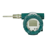
Temperature transmitter (1 input type)
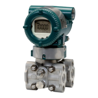
High precision temperature transmitter (1 input type)
High precision temperature transmitter (2 input type)
Output
signal
–D . . . . . . . . . . . . . . . . . . . .
–E . . . . . . . . . . . . . . . . . . . .
–F . . . . . . . . . . . . . . . . . . . .
4 to 20mA DC output, BRAIN communication type
4 to 20mA DC output, HART communication type
FOUNDATION Fieldbus communication type
*1
A . . . . . . . . . . . . . . . . . Always A
Electrical
connection
0 . . . . . . . . . . . . . . .
2 . . . . . . . . . . . . . . .
3 . . . . . . . . . . . . . . .
4 . . . . . . . . . . . . . . .
G1/2 female
1/2 NPT female
Pg13.5 female
M20 female
Built-in indicator
D . . . . . . . . . . . .
N . . . . . . . . . . . .
Digital indicator
None
Mounting bracket
B . . . . . . . . . SUS304 2B pipe mounting
*2
None
N . . . . . . . . .
Additional specifications
/ Additional specifications
T0703.EPS
. . . . . . . . . . . . . . . . . . . . . .
. . . . . . . . . . . . . . . . . . . . . .
. . . . . . . . . . . . . . . . . . . . . .
—
*1: Applicable for YTA320 only.
*2: Use bolts for wall mounting.
7.3 Optional Specifications
Item
Descriptions
Code
Lightning protector
A
Painting
Coating change X1
Color change
P1
Calibration Unit
D2
Sensor matching function*
2
CM1
Output signal low-side in
C1
Transmitter failure*
2
P7
P2
Munsell renotation code
: NI1.5 Black
Metallic silver
T0704.EPS
YTA110
YTA310
YTA320
䊊
䊊
䊊
䊊
䊊
䊊
䊊
䊊
䊊
䊊
䊊
䊊
䊊
䊊
䊊
䊊
䊊
Power supply voltage: 10.5 to 32 V DC
Allowable current: Max. 6000A(140s),
repeating 1000A(140s) 100 times
Output signal low-side: -5 %, 3.2 mA DC or less.
Sensor burnout is also set to ' LOW ': -2.5 %, 3.6 mA DC
RTD Sensor matching function
Degree F/Degree R unit
Epoxy resin coating
Munsell renotation code
: 7.5BG4/1.5, Jade green
Amplifier
cover
only
Stainless Steel Housing*
1
Housing Material : SCS14A Stainless steel
E1
*1 : Not applicable with other option codes, except for A, C1, D2 and CM1.
*2 : Not applicable for output signal code F.

 Loading...