IM 01C50B01-01E
2-11
2. NOTES ON HANDLING
Note 3. Operation
• Keep strictly the “WARNING” on the nameplate
attached on the transmitter.
WARNING: OPEN CIRCUIT BEFORE RE-
MOVING COVER. “FACTORY
SEALED, CONDUIT SEAL NOT
REQUIRED”. INSTALL IN ACCOR-
DANCE WITH THE INSTRUCTION
MANUAL IM 1C50B1.
• Take care not to generate mechanical spark when
access to the instrument and peripheral devices in
hazardous location.
Note 4. Maintenance and Repair
• The instrument modification or parts replacement by
other than authorized representative of Yokogawa
Electric Corporation is prohibited and will void
Factory Mutual Explosionproof Approval.
2.7.5 JIS Certification
a) JIS Flameproof Type
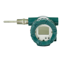
The model YTA /JF3 temperature transmitter, which
has obtained certification according to technical criteria
for explosion-protected construction of electric machin-
ery and equipment (Standards Notification No.556
from the Japanese Ministry of Labor) conforming to
IEC standards, is designed for hazardous areas where
explosive gases and/or inflammable vapors may be
present. (This allows installation in Division 1 and 2
areas)
To preserve the safety of flameproof equipment
requires great care during mounting, wiring, and
piping. Safety requirements also place restrictions on
maintenance and repair activities. Users absolutely
must read “Installation and Operating Precautions for
JIS Flameproof Equipment” at the end of this manual.
WARNING
The terminal cover should not be opened at
least for three minutes after the power is turned
off.
The terminal section of the flameproof YTA
series is made of resin-filled, explosion-protected
construction. The technical standards for this
flameproof construction require that the possibil-
ity of explosion resulting from a prospective
short-circuit current
*2
of up to 4000 A be pre-
vented even for cases when external power
supply circuits are short-circuited accidentally.
Install a fuse or a circuit breaker having a
breaking capacity of at least 4000 A in the
higher-order power line connected to the YTA
series. The breaking capacity refers to the upper
limit of current that can be cut off. Normally, a
fuse or a circuit breaker having a breaking
capacity of greater than 5000 A is used in power
supply circuits. Confirm that this is true with your
factory. No extra measures need be taken after
the confirmation.
Note that the rated current of the YTA series in
terms of explosion protection is 4 to 20 mA;
keep the input current of the YTA series within
the appropriate range.
*2: Refers to a current that flows when a fuse in a circuit is
substituted with a connecting metal piece having virtually no
impedance and the circuit is then shorted. For AC circuits, this
current is represented by a root-mean-square value (JIS C6575).
2.7.6 SAA Certification
Model YTA110/SU1, YTA310/SU1 and YTA320/SU1
temperature transmitters can be selected the type of
protection (SAA Intrinsically Safe, Type of Protection
“n” or Flameproof) for use in hazardous locations.
Note 1. For the installation of this transmitter,
once a particular type of protection is
selected, any other type of protection
cannot be used. The installation must be
in accordance with the description about
the type of protection in this instruction
manual.
Note 2. In order to avoid confusion, cross out
unnecessary marking on the label other
than the selected type of protection when
the transmitter is installed.
a) SAA Intrinsically Safe/Type N Type
Caution for SAA Intrinsically safe/Type n type
Note 1. Model YTA110/SU1, YTA310/SU1 and
YTA320/SU1 temperature transmitters for
potentially explosive atmospheres:
• Type of Protection and Marking code:
Ex ia IIC T4 (Tamb=70°C) IP66/67 Zone 0
Ex n IIC T4 (Tamb=70°C) IP66/67 Zone 2
• Ambient Temperature: –40 to 70°C
Note 2. Entity Parameter
• In type of explosion protection only for connection
to a certified intrinsically safe/type n circuit with
following maximum values:
[Input parameters (terminals +&-/C)]
Maximum Input Voltage(Ui) = 30 V
Maximum Input Current(Ii) = 165 mA
Maximum Input Power(Pi) = 0.9 W
Maximum Internal Capacitance(Ci) = 30.2 nF
Maximum Internal Inductance(Li) = 738 µH
 Loading...


