Replacing Parts
Replacing the Feed Switch Circuit Board
44
980618-001 A Thermal Transfer G-Series
TM
Service Manual 8/27/08
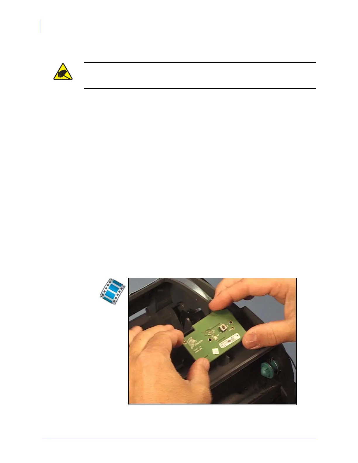
Replacing the Feed Switch Circuit Board
You must remove the top cover before performing this procedure.
Removal
1. Use a #1 Phillips screwdriver to remove the two screws securing the circuit board to the
top, inner frame.
2. Lift the front of the board up to access the ribbon cable connectors.
3. Open the connector to the media sensor and pull the ribbon cable out.
4. Open the connector to the Main Logic circuit board and pull the ribbon cable out.
Installation
1. Make sure the ribbon sensor cable is secured into its clip.
2. Align the feed button board with the ribbon connectors to the rear.
3. Plug the media sensor cable into its connector and lock it into place.
4. Plug the flex cable going to the Main Logic circuit board (right side) into its connector on
the feed switch circuit board and lock it into place.
5. Lower the feed button board onto the top, inner frame. Replace the screws that hold the
board and use a #1 Phillips screwdriver to tighten them.
Replace the top cover. Reload media. Plug in power, turn on the printer and print a status
report to ensure proper function.
Caution • Prepare your work area by protecting against static discharge. Your work area
must be static-safe and include a properly grounded conductive cushioned mat to hold the
printer and a conductive wrist strap for yourself.
 Loading...