Replacing Parts
Replacing the Cover Assembly
68
980618-001 A Thermal Transfer G-Series
TM
Service Manual 8/27/08
Replacing the Cover Assembly
You must remove the bottom case, top case, Main Logic circuit board, and hinges before
performing this procedure.
Removal
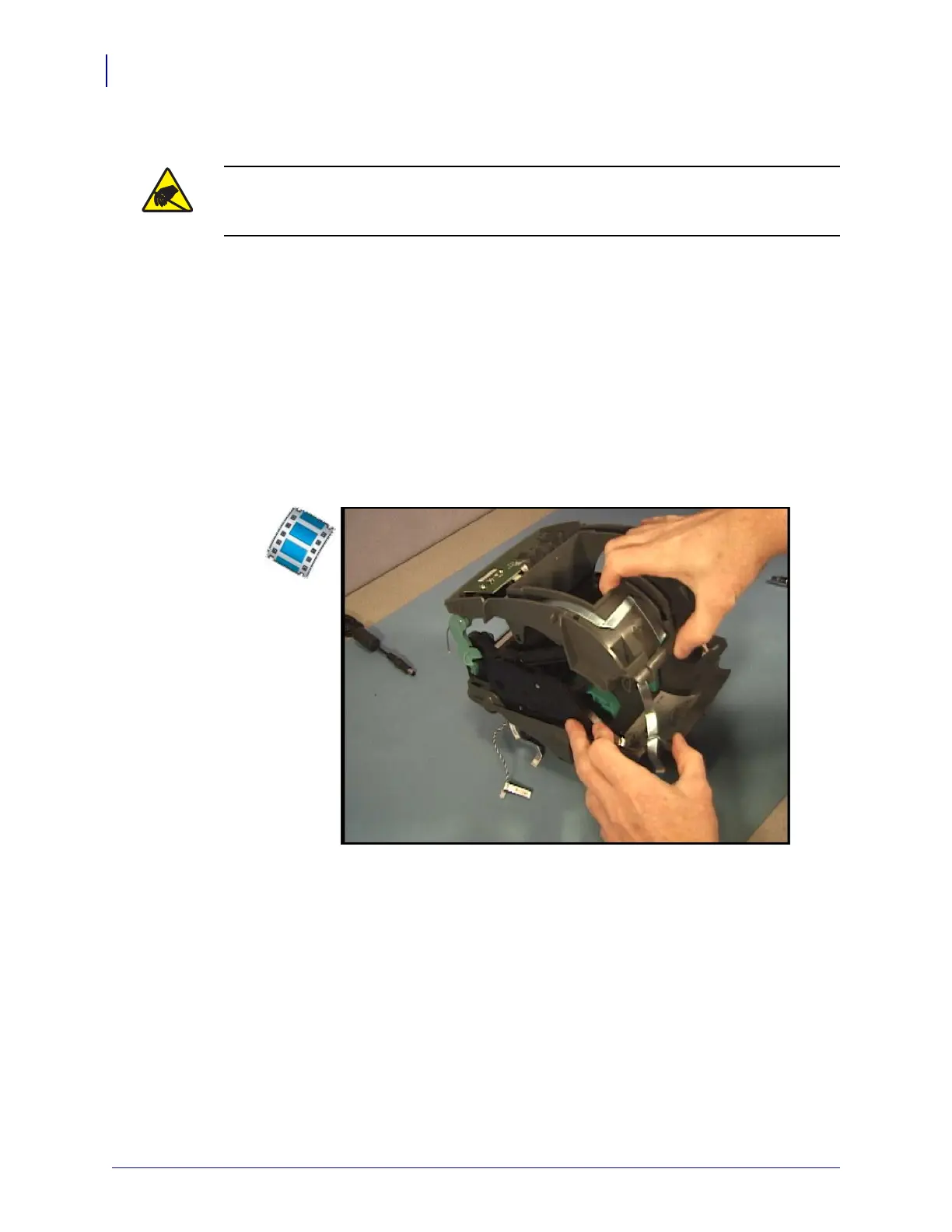
1. After removing the bottom case, top case, Main Logic circuit board, and hinges; detach
both the left and right links on the ribbon carriage from the top, inner frame.
2. Pull the top, inner frame away from the (lower) print mechanism and ribbon carriage
assembly.
Installation
1. Lower the top, inner frame over the ribbon carriage. Make sure the flapper slides into its
guide track on the ribbon carriage.
2. Attach the links on both the left and right sides.
Replace the hinges, Main Logic circuit board, top case and bottom case.
Reload media. Plug in power, turn on the printer and print a status report to ensure proper
function.
Caution • Prepare your work area by protecting against static discharge. Your work area
must be static-safe and include a properly grounded conductive cushioned mat to hold the
printer and a conductive wrist strap for yourself.
 Loading...