45
Replacing Parts
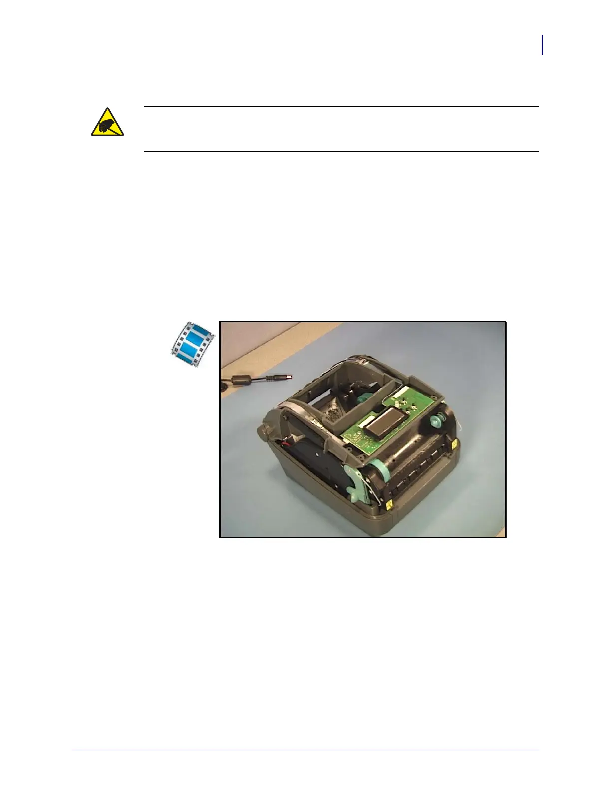
Replacing the LCD/Feed Switch Circuit Board
8/27/08 Thermal Transfer G-Series
TM
Service Manual 980618-001 A
Replacing the LCD/Feed Switch Circuit Board
This procedure applies to both Wi-Fi 802.11 b/g and Bluetooth printer configurations.
You must remove the top cover before performing this procedure.
Removal
1. Use a #1 Phillips screwdriver to remove the two screws securing the LCD/Feed Switch
circuit board to the top of the printer chassis.
2. Release the locks on the three ribbon cables and pull the cables free of the circuit board.
3. For Wi-Fi 802.11 b/g printer models: Disconnect the antenna from the circuit board.
Installation
1. Open the three cable connector’s cable locks. Insert the flex cables into the connectors
with the cables contacts (fingers) facing the LCD PCBA. Lock the connectors.
2. For Wi-Fi 802.11 b/g printer models: Connect the antenna from the circuit board.
3. Verify all ribbon cables are inserted straight in the connectors and are not pulled out.
4. Flip the circuit board over and mount to the printer chassis. Secure it with the two screws.
Replace the top cover. Reload media. Plug in power, turn on the printer and print a status
report to ensure proper function.
Caution • Prepare your work area by protecting against static discharge. Your work area
must be static-safe and include a properly grounded conductive cushioned mat to hold the
printer and a conductive wrist strap for yourself.
 Loading...