12
Main LCD & Wheel LCD
The Main LCD provides part of the user interface on the front panel of the desk. The content, layout, operation and
other information displayed on this screen is dependent on the current operation being carried out on the desk.
In Setup, the Main LCD acts as a guide showing where you are in the Setup menu structure and gives instructions
on what to do.
When the Memories or Submasters screen are selected, the Main LCD acts as a small viewing portal on the Memories
or Submasters window.
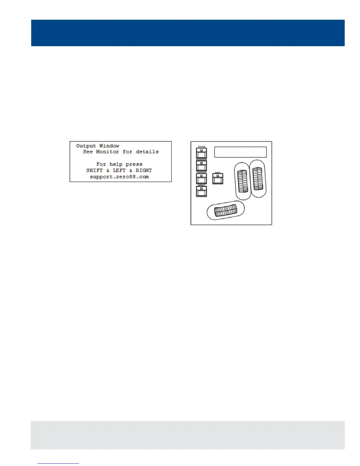
When any of the other main windows (Program Window, Outputs, Groups etc.) are selected, the Main LCD displays a
simple text message directing you to refer to the monitor, plus the desk software version and other helpful information,
for example:
Wheel LCD
The Wheel LCD is used to indicate which xture parameters or other data are being controlled by each of the three
control wheels.
Example - When showing xture parameter values - The Wheel LCD displays the parameter name (eg Colour1) and
the value in %, DMX or the parameter detail name.
Tag status is shown by inverse graphics – an inverted display shows a tagged parameter, and a true colour display
shows an untagged parameter.
Control Wheels
The three control wheels are used for setting xture parameter levels and other data. The names of the xture
parameters or other data currently assigned to each of the wheels and their values is shown on the Wheel LCD.
Wheel Editing Modes
There are a number of wheel editing modes which apply when editing several xtures at the same time (Absolute,
Relative, Fan First, Fan Middle, Fan Last, Fan V).
For each attribute there is a normal wheel mode which applies when the control wheel is moved and a shifted wheel
mode which applies when the SHIFT key is held down and the control wheel is moved.
For further details on each of the wheel editing modes, and how to adjust the normal and shifted mode for each
attribute – see page 82 of the full user manual for full details.
Figure 10 - Main LCD
Figure 11 - Wheel LCD