Installation and Operating Instructions V03 35
1. Loosen the screws of the cover using a screwdriver (T25) and remove the cover.
(see Section 5 " Electrical Connection ").
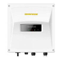
2. Unscrew the swivel nut of the M25 cable gland, remove the filler-plug from the
cable gland and keep it well. If there is only one network cable, please keep a
filler-plug in the remaining hole of the sealing ring against water ingress.
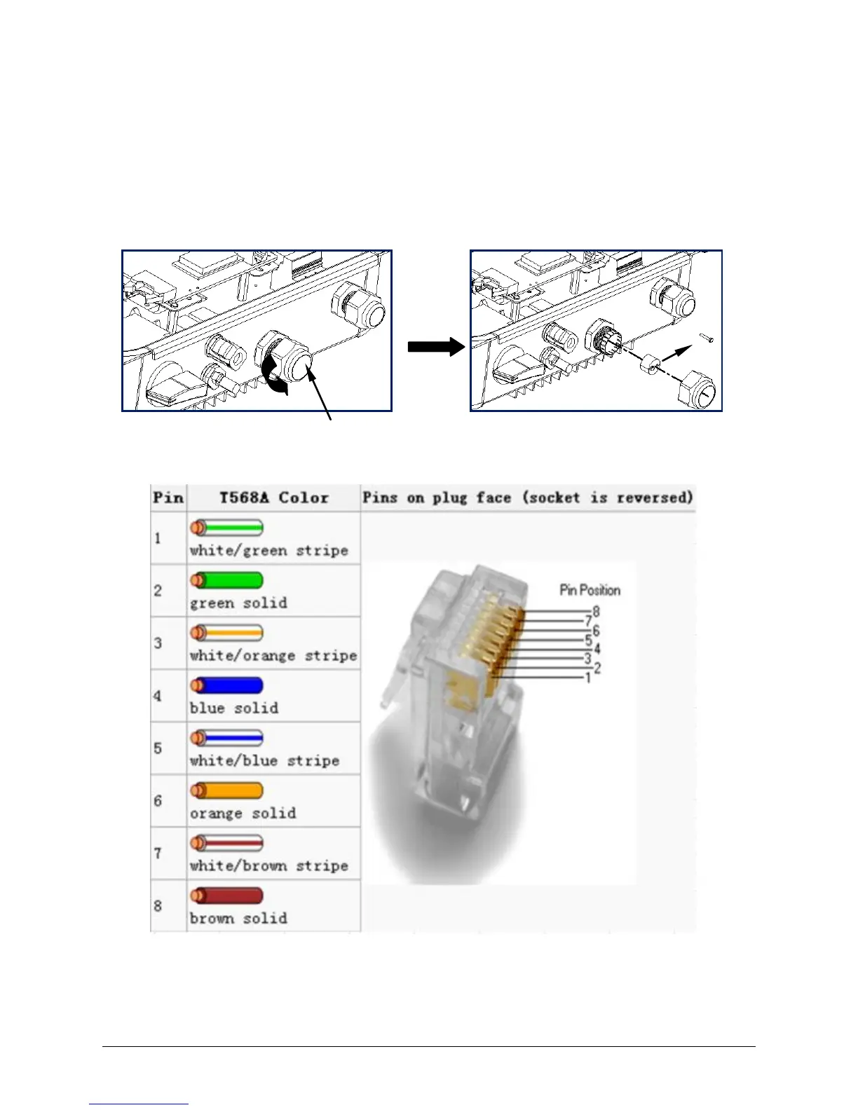
3. Current pin assignment for the network cable as per EIA/TIA 568 standard:
4. Route the network cable into the inverter through the M25 cable gland, and
connect it to the RJ45 keystone socket on the power-PCBA.
 Loading...