UNItivity 5000 Performing Diagnostics and Testing
User Manual
Copyright © 2022 Zinwave. All rights reserved. 14-3
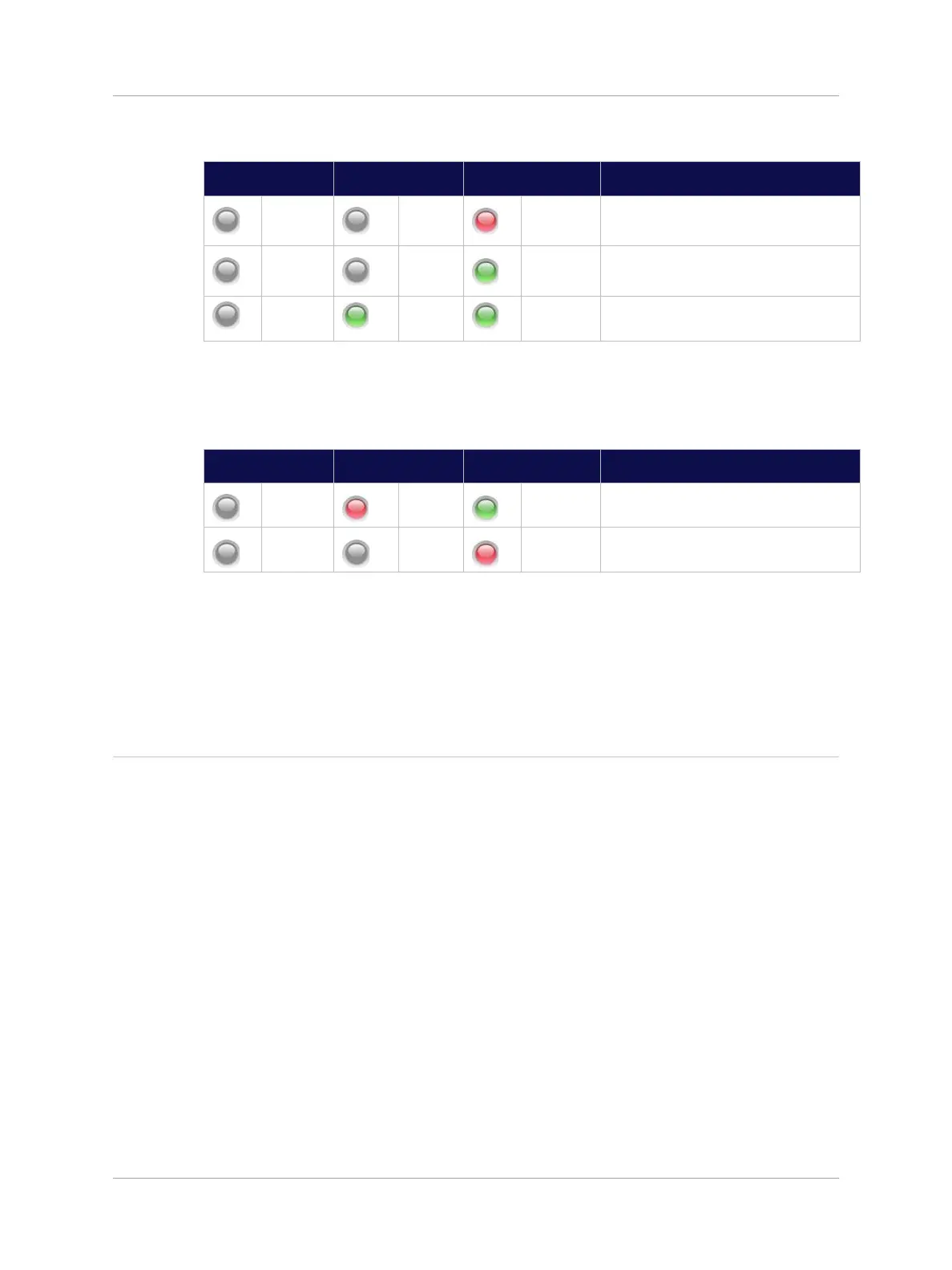
The Service Module LEDs will follow the sequence shown below:
6. Disconnect the optical fiber from the Optical Module connector.
The Optical Module LEDs will alternate between the states shown below:
7. Wait at least 10 seconds then reconnect the optical fiber to the Optical Module. The Optical
Module LEDs will follow the same sequence shown in step 2 above.
Note: It is not possible to initiate a module alarm so the left side LED “RED” state cannot be tested.
14.2.2 Remote Unit LED Test
In order to test the correct operation of the Remote Unit LED, connect the Remote Unit to an Optical
Module in the front of a Primary Hub. The power supply should not be connected.
The following test sequence should be followed:
1. Power up the Remote Unit by plugging in the power supply The LED will follow the sequence:
a. OFF – RED – ALT. RED/GREEN – GREEN FLASH – GREEN
2. Using “System Setup” disable the Remote Unit output
a. The LED will FLASH GREEN
3. Using “System Setup” re-enable the Remote Unit output
a. The LED will go GREEN.
.
 Loading...