UNItivity 5000 Hub and Module LEDs
User Manual
Copyright © 2022 Zinwave. All rights reserved. 3-14
3.4.3 Transport Module
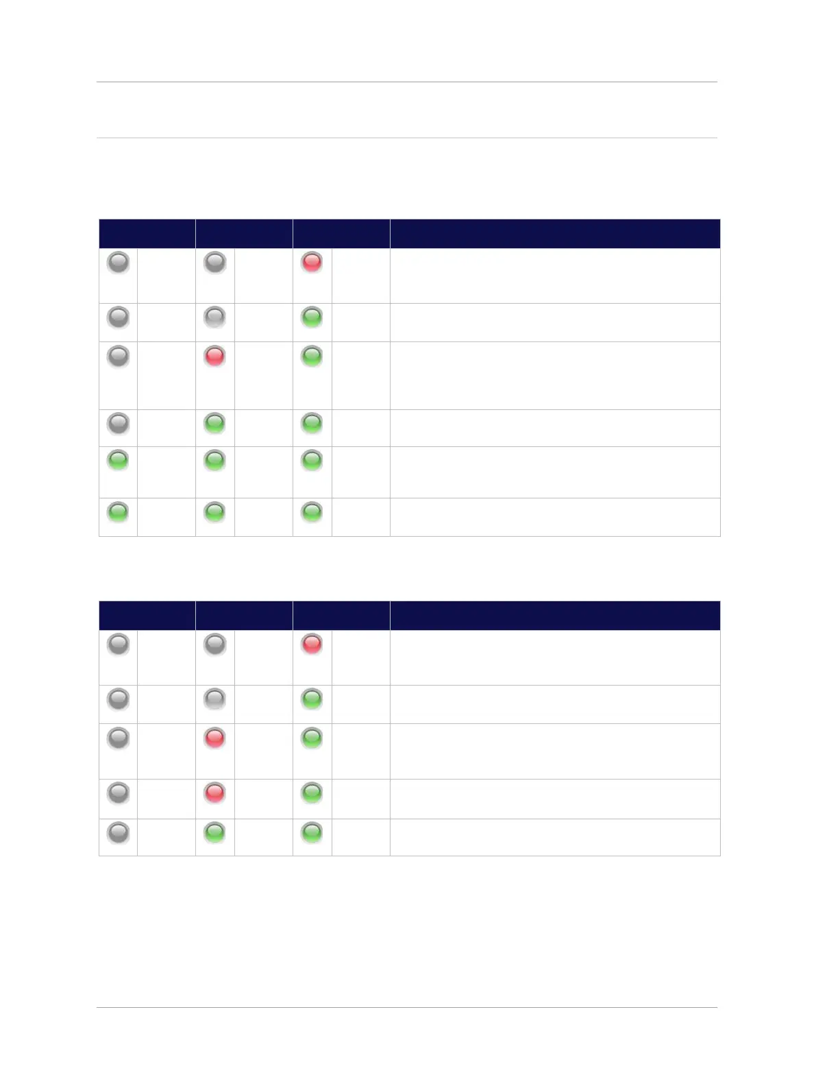
The following table shows a typical LED start up sequence for a fully enabled Transport Module plugged
into the front slot of a UniTransport Hub.
Initial power-up. Power present on Hub allowing
Transport Module to be detected; or
Transport Module NOT Enabled through System Setup.
Transport Module successfully detected, starting
discovery of downstream Primary Hub.
Potential communication failure state: No incoming light
on fiber or no downstream system elements have
responded after several communication attempts
(discovery continues).
Communication success state: communication
established with a downstream Primary Hub.
Optical calibration and auto-setup of downstream units in
progress, and/or RF path to downstream Primary Hub is
disabled.
Transport Module is connected to active downstream
Primary Hub.
The following table shows a typical LED start up sequence for a fully enabled Transport Module plugged
into the rear slot of a Primary Hub.
Initial power-up. Power present on Hub allowing
Transport Module to be detected; or
Transport Module NOT Enabled through System Setup.
Transport Module successfully detected, starting
discovery of downstream Primary Hub.
Potential communication failure state: No incoming light
on fiber or no messages from upstream UniTransport
Hub.
Potential failure state: Hardware Warning Alarm is
present on this Transport Module.
Transport Module is connected to active upstream
UniTransport Hub.