XS1930 Series User’s Guide
35
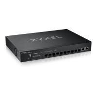
3.1.3 SFP Slots
The transceiver slots are for Small Form-Factor Pluggable (SFP), SFP+ transceivers or DAC (Direct Attach
Copper) cables. The SFP+ (SFP Plus) and the DAC cable are enhanced versions of the SFP and support
data rates of up to 10G. A transceiver is a single unit that houses a transmitter and a receiver. Use a
transceiver or a DAC cable to connect a fiber cable to the Switch. The Switch does not come with
transceivers nor DAC cables. You must use transceivers or DAC cables that comply with the Small Form-
factor Pluggable (SFP) Transceiver MultiSource Agreement (MSA). See the SFF committee’s INF-8074i
specification Rev 1.0 for details.
You can change transceivers or the DAC cables while the Switch is operating. You can use different
transceivers to connect to Ethernet switches with different types of fiber connectors.
• Type: SFP or SFP+ connection interface
• Connection speed: 1 or 10 Gigabit per second (Gbps)
WARNING! To avoid possible eye injury, do not look into an operating
fiber module’s connectors.
HANDLING! All transceivers are static sensitive. To prevent damage from
electrostatic discharge (ESD), it is recommended you attach an ESD
preventive wrist strap to your wrist and to a bare metal surface when
you install or remove a transceiver.
STORAGE! All modules are dust sensitive. When not in use, always keep
the dust plug on. Avoid getting dust and other contaminant into the
optical bores, as the optics do not work correctly when obstructed with
dust.
3.1.3.1 Transceiver Installation
Use the following steps to install a transceiver.
1 Attach an ESD preventive wrist strap to your wrist and to a bare metal surface.
2 Align the transceiver in front of the slot opening.
3 Make sure the latch is in the lock position (latch styles vary), then insert the transceiver into the slot with
the exposed section of PCB board facing down.
4 Press the transceiver firmly until it clicks into place.
5 The Switch automatically detects the installed transceiver. Check the LEDs to verify that it is functioning
properly.
6 Remove the dust plugs from the transceiver and cables (dust plug styles vary).
7 Identify the signal transmission direction of the fiber cables and the transceiver. Insert the fiber cable into
the transceiver.
 Loading...
