1.
2.
3.
4.
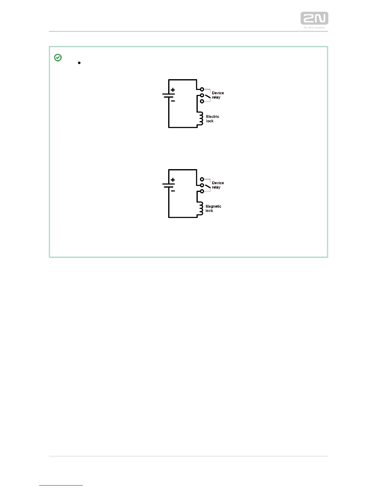
Output wiring diagram for Relay terminals
The electric lock is opened by power supply connection.
The magnetic lock is opened by power supply disconnection.
Terminal Block X2 Connection
Terminal block X2 includes 10 terminals whose functions are distinguished by colour.
Terminals 5–10 are used for connecting to the Ethernet. Terminals 3–4 2N IP Vario
®
are designed for connecting the electric lock and terminals 1–2 help connect an
external 12 V / 2 A DC power supply if no PoE power supply is available.
The terminal block is included in the package. To adjust an already installed
, disconnect it IP from the power supply. Then pull to remove the 2N IP Vario
®
terminal block from the printed circuit board.
Insert the wires under the respective terminals.
Tighten the terminals using a flat screwdriver.
Replace the terminal block to the printed circuit board.