Caution
Make sure that the cables leading through the cover 2N IP Vario
®
bottom groove are installed properly. For the correct installation of the
cables refer to Figure 2.7.
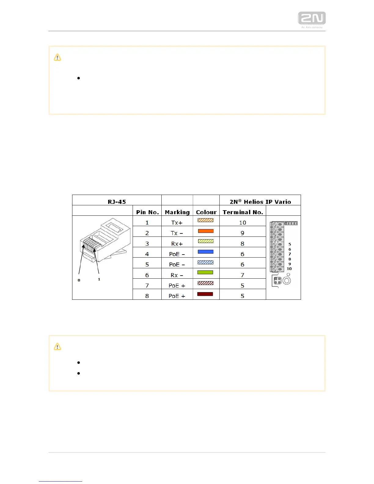
Ethernet Connection
For the connections and meanings of the wires see the table below. Join UTP cable
wires 4 (blue) and 5 (white-blue) and attach them under terminal 6 on In 2N IP Vario
®
the same way, join wires 7 and 8 and place them under terminal 5 of
.2N IP Vario
®
Terminal Block Connections
Caution
We recommend the use of a LAN surge protection.
We recommend the use of a shielded SSTP Ethernet cable.