5.2 Mechanical Alignment of Angle and Extension Sensors
Following the replacement of a potentiometer, even if this has been done carefully, it is suggested to check its alignment.
The following procedure, if properly done, allows the total restoring of the machine behaviour without any calibration
operation.
PROCEDURES STATUS
IN THE CONTROL AREA
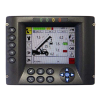
Switch on the machine without load and wait for a few seconds for the main working
data panel monitoring on the display.
Verify Angles
After that, press the key a number of times until the page showing the
readings of sensors digital values is displayed.
With regard to the angle setting, it is simply necessary to check that in horizontal
(=°) positioning of the boom
•
••
• the reading of the sensor “A1adc” is between 100 and 1000 by
rotating its body before fixing it, and that it decreases as the
boom is raised.
A1adc A1act
xxx xxx
Verify Extension
For the extension after replacing the sensor act on its shaft to check that reading
1) on “S1adc” 55
Also, in case of cable replacement it is necessary to pre-tension approximately 1
Mt. of cable-reel cable fixing opposite end at the position where reading of the
sensor “S1adc” 55.
Check:
when extend the value S1adc increase
S1adc S1act
xxx xxx
After the replacement of the sensor it is recommended to verify the correspondence of values shown on the display into
a couple of known positioning of the boom.
I.E.: boom IN and boom OUT, or Boom lower position (Min Angle) and Boom Upper Position (Max Angle) .
These displayed values must correspond to the values given by the Manufacturer for this specific model of the machine.
 Loading...