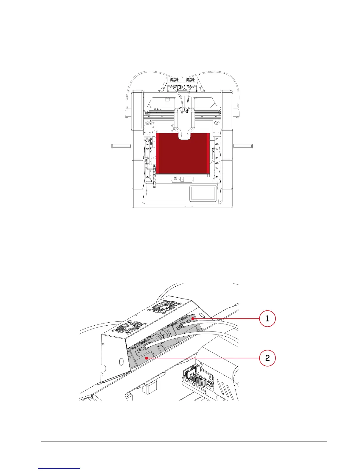
1.2. Heatbed
The printer's heatbed moves along Y axis and Z axis (fig. 12). The entire heatbed is marked with a lighter colour. The darker
colour marks the actual printing area. The difference between the heatbed area and the actual printing area in X axis results
from the use of the dual hotend system. Made of ceramic plate, the heatbed guarantees good printout adhesion even for
several dozen hours of continuous operation of the printer.
Fig. 12 Heatbed of 3DGence DOUBLE P255 printer
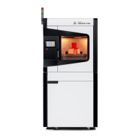
1.3. Extruders
3DGence DOUBLE P255 printer is equipped with two material extruding systems (Bowden type extruders) (fig. 13). They are
located on the printer's top, behind the dual hotend module. Extruder T0 (Tool 0) is responsible for feeding the base material
to hotend T0, while extruder T1 (Tool 1) is responsible for feeding the supporting material to hotend T1. Tool 0 extruder is
located on the left side of the user facing the printer (fig. 13). More information on loading the materials and operation of
extruders can be found in chapter III, point 4.
Fig. 13 Extruders of 3DGence DOUBLE P255 printer 1. Extruder T1 | 2. Extruder T0