VI DUAL HOTEND MODULE
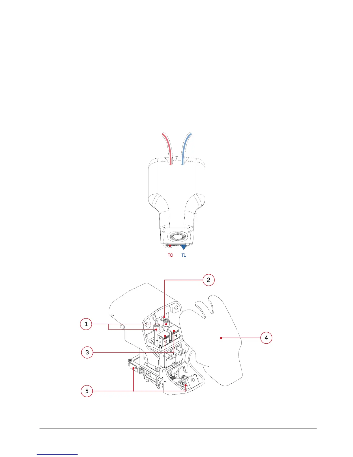
The dual hotend module is a permanent element of 3DGence DOUBLE P255 printer. T0 hotend, which is responsible for
plasticizing the base material, is located on the left side of the user facing the printer (in fig. 47, the hotend is in the inactive
position, marked in red). On the right side, there is T1 hotend responsible for plasticizing the support material (in fig. 47, the
hotend is in the active position, marked in blue). Other key elements of the dual hotend module are shown below (fig. 48, 49).
To get access to the module, dismount the front casing mounted on magnets. As standard, the module is equipped with two
replaceable 3DGence hotends with the nozzle diameter of 0.4 mm. The complete system, thanks to its driving servo-
mechanism, is able to automatically switch the printer to printing with one of the two materials in a short time. The servo-
mechanism drive rises and lowers the hotends using a special cam. The hotends are connected to the extrusion system by
means of the guiding sleeves. Stoppers prevent the material from flowing out of the inactive hotend. Additionally, the module
has a printout cooling system and integrated strain gauge system responsible for autocalibration and autocompensation
measurements. The module is also equipped with the PUSH system - the quick hotend change system. More information on
the hotend change can be found in chapter VI, point 1.
Fig. 47 Dual hotend module - front view
Fig. 48 Dual hotend module: 1. Guiding sleeves | 2. Mechanism cam
3. PUSH keys | 4. Front casing (attachable part) | 5. Printout cooling fans