VII COMPLEMENTARY INFORMATION
1. AUTOCOMPENSATION AND AUTOCALIBRATION
The heatbed scanning procedure is performed for each printer in the manufacturer's factory. To ensure the best possible print
quality, it is recommended that the procedure should be repeated every several hundred working hours of the printer. The
procedure should be also repeated in the case of problems with adhesion of printouts to the heatbed or when the material is
laid unevenly by the printer while printing the first layers.
3DGence DOUBLE P255 printer is equipped with advanced algorithm for autocalibration and autocompensation of the heatbed.
The heatbed scanning procedure must be performed in order to ensure correct autocompensation. The procedure is described
below.
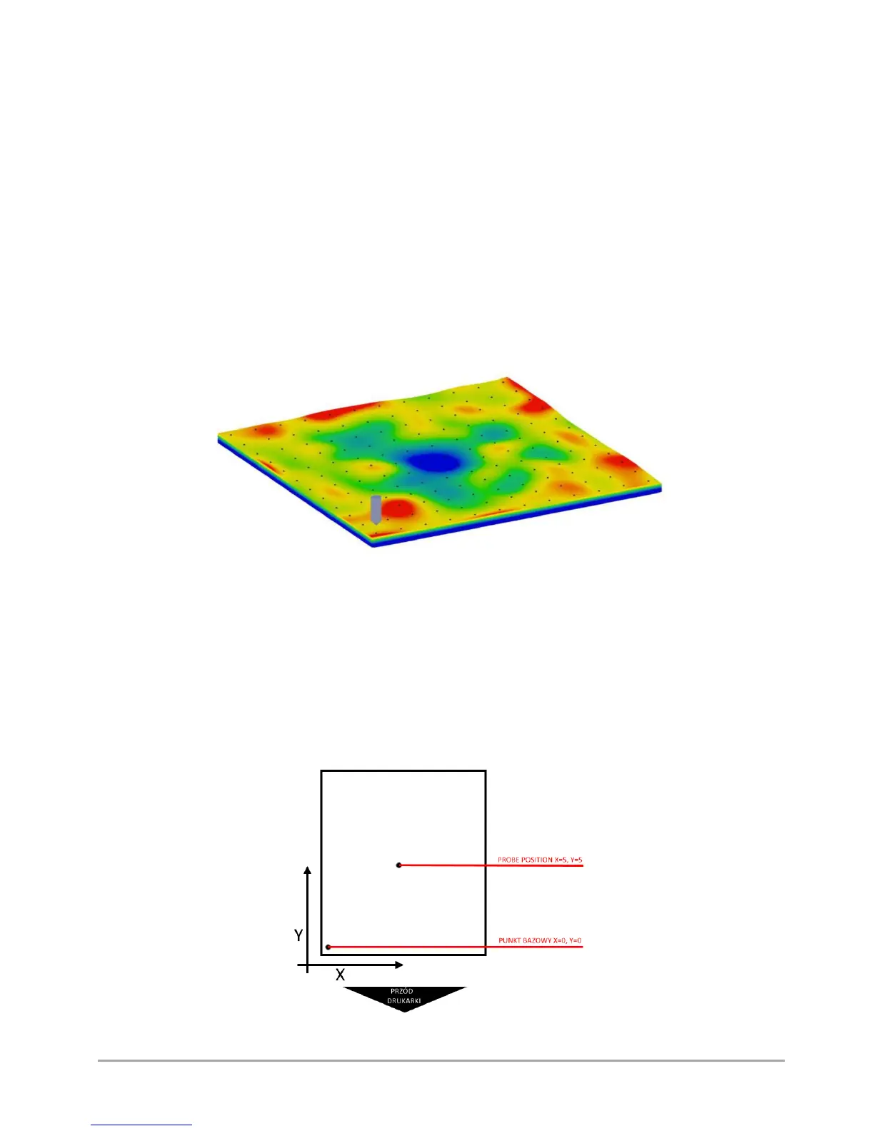
Autocalibration of the heatbed is the automatic measurement of the heatbed surface in 100 points with the use of a pressure
sensor built into the printing module. Based on this measurement, the virtual map of the heatbed curvature is created, which
is the basis for the autocalibration and autocompensation. The map is saved in the printer's memory and is modified only after
performance of a next complete working scan (fig. 55).
Fig. 55 The map of the heatbed curvature resulting from autocalibration
Autocompensation of the heatbed consists in one-point measurement of the distance to the heatbed and determining the
correct distance to start work. This process takes place each time before printing. After setting the correct height above one
point, the next part of the printing process is performed taking into account the heatbed curvature pattern saved in the printer
memory – thanks to this, the distance between the nozzle and the heatbed is always the same and corrected on an ongoing
basis along the Z axis.
It is possible to set the autocompensation measuring point (fig. 56).
By default, the autocompensation point is set at the centre of the heatbed. To modify the autocompensation point, go to
MENU → ADVANCED → AUTOCOMP. SETTINGS and choose X PROBE POSITION. Set the measuring point from 1 to 10, choose
Y PROBE POSITION (set 1 - 10) and confirm with CONTINUE key.
Fig. 56 Example of autocompensation measuring point