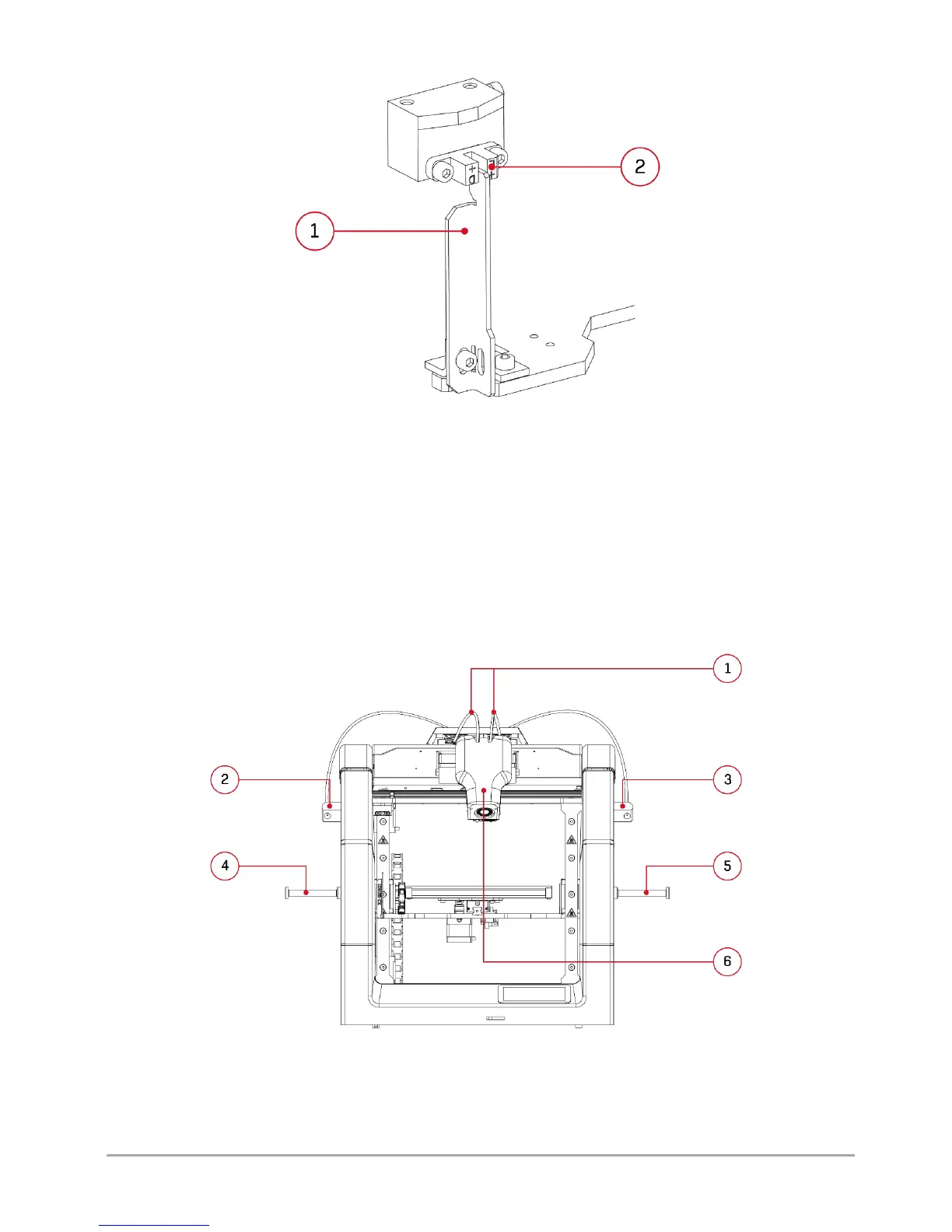
Fig. 6 1. Z axis breaker | 2. Z axis endstop - in its correct home position
II PRINTER DESCRIPTION
1. DESIGN OF PRINTER
The figures together with the descriptions of the major printer's components are presented below in order to facilitate the
operation of 3DGence DOUBLE P255 printer and make it easy to understand the instructions included in the User's Manual (fig.
7-10). Please, refer to the figures and descriptions in order to better understand the 3D printing terminology.
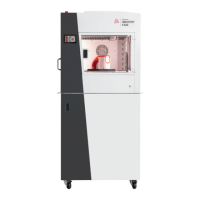
Fig. 7 3DGence DOUBLE P255 printer – front view.
1. Bowden tubes | 2. Filament sensor T0 | 3. Filament sensor T1
4. Spool holder T0 | 5. Spool holder T1 | 6. Printing module