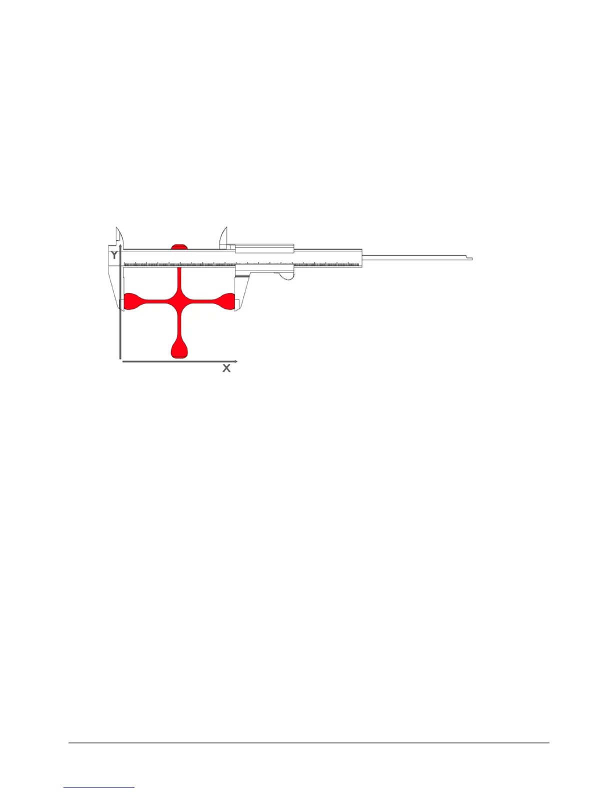
After printing, cooling down and removing the calibration cross carefully from the heatbed, measure the cross along X and Y
axes. They are marked on the model. Different tools can be used to make the measurement, but their accuracy must be at
least 0.05 mm:
• slide caliper,
• micrometer,
• coordinate measuring machine,
• optical tools.
The printout should be measured along X and Y axes. To increase the measurement certainty, follow the below instructions:
• the measuring point should be in the middle of the model height above the step, both points at the height of the same
layer (fig. 59),
• measurements for X and Y axes should be made 5 times for each axis. Reject the highest and the lowest measurement
result from each group. Other measurements should be averaged for each axis (fig. 60).
Fig. 60 Table of measurements for X axis and Y axis
The result of such action will be the basis for further operations:
1. Go to MENU → ADVANCED → XY CALIB. (fig. 25).
2. Choose ORIGIN X and use –/+ keys to enter the value of the dimension given to the model in X axis. In the case of
Dimmension_Calibration.stl file downloaded from the website, this value is 100,00 mm.
3. Choose PRINT X and use –/+ keys to enter the value measured on the cross in X axis.
4. Choose ORIGIN Y and use –/+ keys to enter the value of the dimension given to the model in Y axis. In the case of
Dimmension_Calibration.stl file downloaded from the website, this value is 100,00 mm.
5. Choose PRINT Y and use –/+ keys to enter the value measured on the cross in Y axis.
6. Confirm the changes with the Save key.
Additionally, in order to verify correct axis calibration, you can print the Dimmension_Calibration.stl model downloaded from
the website once again and measure it.
Thanks to this procedure, the next printout of the material for which calibration was performed will be printed with
compensation of material shrinkage along X and Y axes.