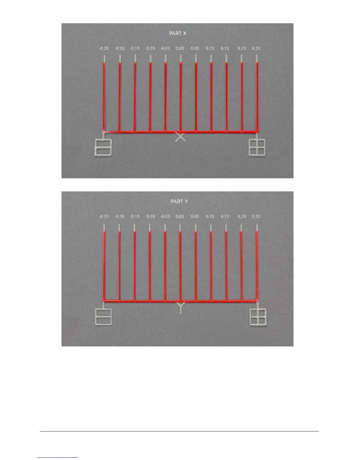
Fig. 62 Calibration model of offset along X axis
Fig. 63 Calibration model of offset along Y axis
Figure 63 presents two calibration models – part X.
The first one (at the top) has incorrect offset values along the X axis, while the second one (at the bottom) has correctly
calibrated offset values along the X axis (fig. 64).
With correctly calibrated offsets on the middle line (point 0.00), the model material coincides with the support material both
in the X axis and in the Y axis (Fig. 64, bottom model).
First of all, on the out of calibrated model find the line on which the model material (fig. 64, red) is best covered with support
material (fig. 64, white). On the top model (fig. 64), the materials overlap best on the third line to the left of point 0.00. This
line is distanced from point 0.00 at -0.15mm. This means that the X offset value is shifted by -0.15 mm and by this value the X
offset value entered in the calibration menu must be corrected (the offset procedure in the X and Y axis is described below).