Introduction
19
Planning Aastra 400 DECT systems as of R1.0
syd-0457/1.0 – R1.0 – 10.2012
Aastra DECT cordless phones, as well as GAP-mode DECT cordless phones from
third-party manufacturers, can be logged on to an Aastra 400 communication
server.
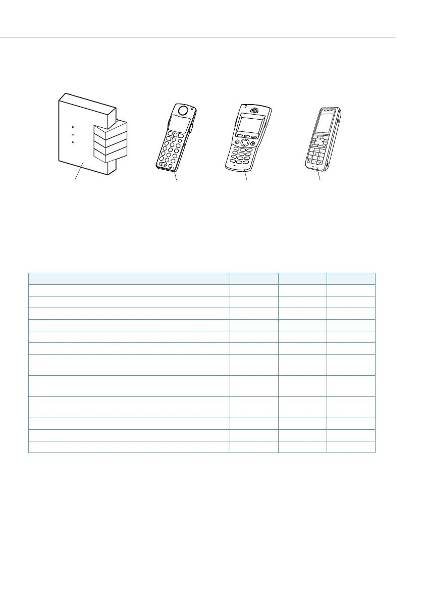
Fig. 1 DECT radio unit and cordless system phones
The following three DECT radio units can be operated on the DSI interfaces of an
Aastra 400 communication server:
Tab. 1 Aastra 400 DECT radio units
Features SB-4+
1)
1)
Radio unit SB-4 is no longer supported on Aastra 400 communication servers.
SB-8 SB-8ANT
Number of simultaneous call connections 4 8
2)
2)
Only if the GAP compatibility mode (zero blind slot mode) is switched off. Otherwise only six channels.
8
2)
Number of DSI interfaces required 1 1
3)
or 2
3)
Only 4 call connections are possible simultaneously in the event of a connection via one DSI interface
1
3)
or 2
Status display with LED ✔✔✔
Disconnectable LED display (normal mode) ✔✔✔
Automatic upload of new system software ✔✔✔
Plug-in power supply unit for local power supply ✔✔✔
Power requirements from the communication server with local
power supply to the radio unit
<100 mW <100 mW <100 mW
Power requirements from the communication server
4)
without
local power supply to the radio unit
4)
The value applies to radio units with hardware version "-2". The values for hardware version -1 are slightly
lower.
1700 mW 1550 mW per
DSI bus
1550 mW per
DSI bus
Max. length of DSI bus
5)
for operation without local plug-in
power supply unit
5)
Depending on diameter and HW version. For more information, see the chapter "DSI terminal interface" in
the Aastra 415/430 or Aastra 470 System Manual.
600 to 1200 m 660 to 1200 m 660 to 1200 m
Alarm following the failure of a local plug-in power supply unit ✔✔✔
External antenna connections – – 2
GAP compatible ✔✔✔
Oce 135
Oce 135pro
Oce 160pro
Oce 160Safeguard
Oce 160ATEX
Aastra 610d/612d
Aastra 620d/622d
Aastra 630d/632d
Radio unit
 Loading...


