DECT Measuring Device ME-8 (test kit)
51
Planning Aastra 400 DECT systems as of R1.0
syd-0457/1.0 – R1.0 – 10.2012
Operating State Display with LEDs
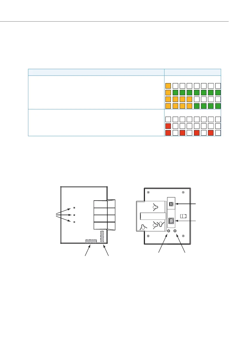
A test radio unit, like a normal radio unit, is fitted with 3 LEDs. The operating state is
indicated by different colours and flashing sequences in cycles of 1 second. Each
character (G=green, R=red, O=orange, - =off) corresponds to 1/8 of a second.
Tab. 3 Flashing sequences of the pilot LED on the test radio unit
Control elements and extensions of the test radio unit
Fig. 19 Views and extensions of the test radio unit
Significance of the flashing sequence Cycle
Middle LED:
Test mode active (internal antenna, no connection)
Test mode active (external antenna, no connection)
Test mode active (internal antenna, 1 or more connections)
Test mode active (external antenna, 1 or more connections)
Outer LED:
Normal state or radio unit has disconnected
1)
1)
If the voltage of the battery falls below a certain level, the power of the radio unit is switched off to con-
serve the battery. All LEDs of the radio unit are then switched off.
Power supply critical (battery soon empty)
Error
Front view
Rear view
Power supply
HEX rotary switch
Pilot LED
Internal
antenna 2
Internal
antenna 1
External antenna
connection 1
External antenna
connection 2
 Loading...


