Electrical connections
32 265Gx, 265Ax IM/265Gx/Ax-EN-07
5.4 Assembling and connecting the socket connector
The socket connector for connecting the cable is supplied unassembled as an accessory for the
transmitter.
IMPORTANT (NOTE)
Please observe the specifications for the electrical connection that have been supplied with
the connector.
Assembly is depicted in the figure below.
1. The contacts (2) are crimped or soldered onto the cable ends (wire cross-section of
0.75 … 1 mm
2
(AWG 18 … AWG 17)), from which approx. 1.5 … 2 cm (0.59 … 0.79 inch) of
the sleeve and approx. 8 mm (0.32 inch) of the insulation have been stripped; they are then
inserted into the socket (1) from the rear.
2. Slide the set screw (6), clamping ring (5), gasket (4), and housing (3) onto the cable in the
order indicated before assembly (you may have to adjust the gasket (4) to fit the cable
diameter).
IMPORTANT (NOTE)
Before you press the contacts completely into the socket, check the connection points again.
Incorrectly inserted contacts can be removed by using a press-out tool (part no.: 0949 813), or
a standard ballpoint pen as a makeshift tool.
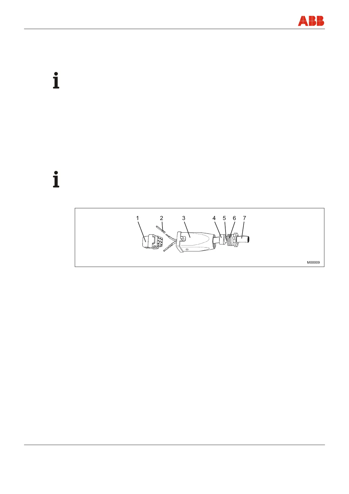
Fig. 11: Assembly of Han 8D (8U) socket connector
1 Socket
2 Contact
3 Housing
4 Gasket (can be cut)
5 Clamping ring
6 PG 11 set screw
7 Cable (diameter 5 … 11 mm
(0.20 ... 0.43 inch))