Configuration
IM/265Gx/Ax-EN-07 265Gx, 265Ax 47
K
7 Configuration
WARNING - Potential property damage as a result of electrostatic charging!
There is no protection against accidental contact when the housing cover is open.
Do not touch conductive parts.
7.1 Factory settings
Transmitters are calibrated at the factory to the customer's specified measuring range. The
calibrated range and measuring point number are provided on the name plate. If this data has
not been specified, the transmitter will be delivered with the following configuration:
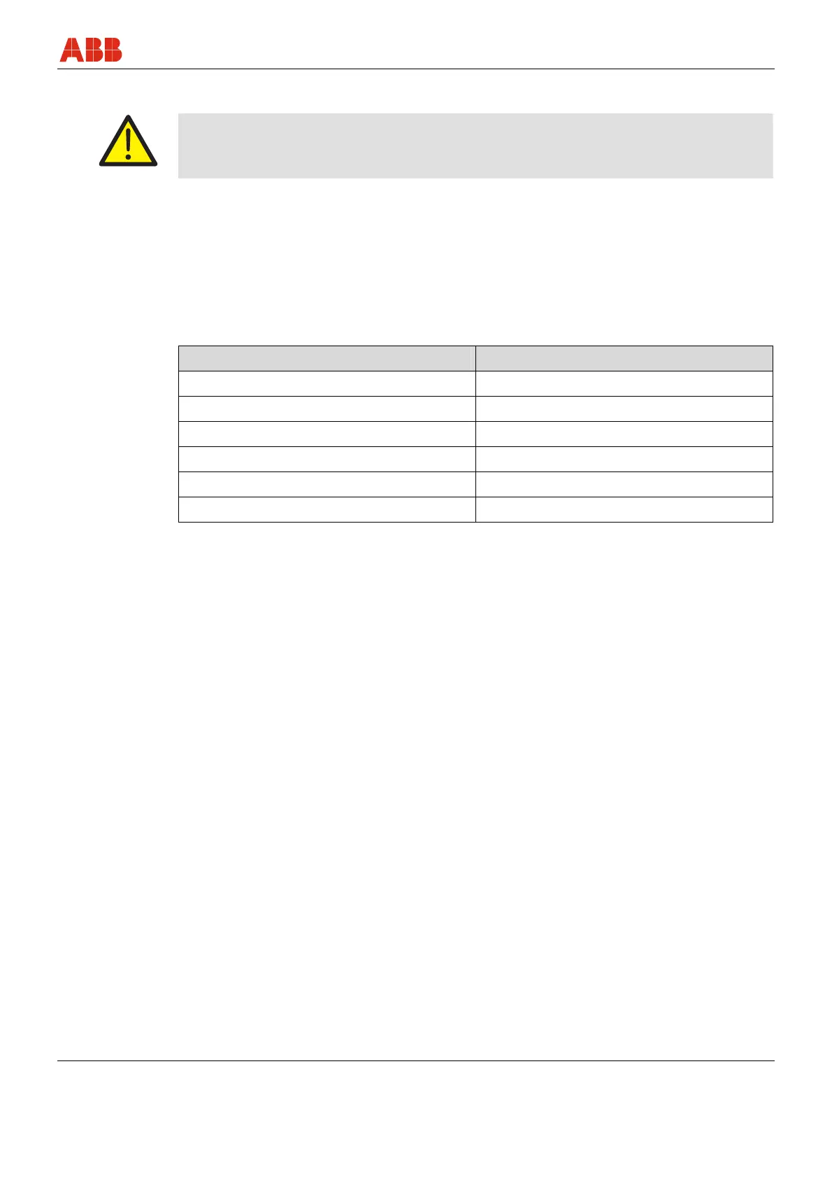
7.1.1 Transmitter with HART communication and 4 … 20 mA output current
Parameter Factory settings
4 mA Zero position
20 mA Measuring range upper limit (URL)
Output Linear
Damping 0.125 s
Transmitter failure mode 21 mA
Optional LCD display 0 … 100 %, linear
Any or all of the configurable parameters listed above - including the “Lower Range Value” and
“Upper Range Value” - can easily be changed using a portable HART handheld terminal or the
PC operation software SMART VISION with DTM for 2600T. Data regarding flange type and
material, O-ring materials, and type of filling liquid is stored in the device.