Specifications
IM/265Gx/Ax-EN-07 265Gx, 265Ax 77
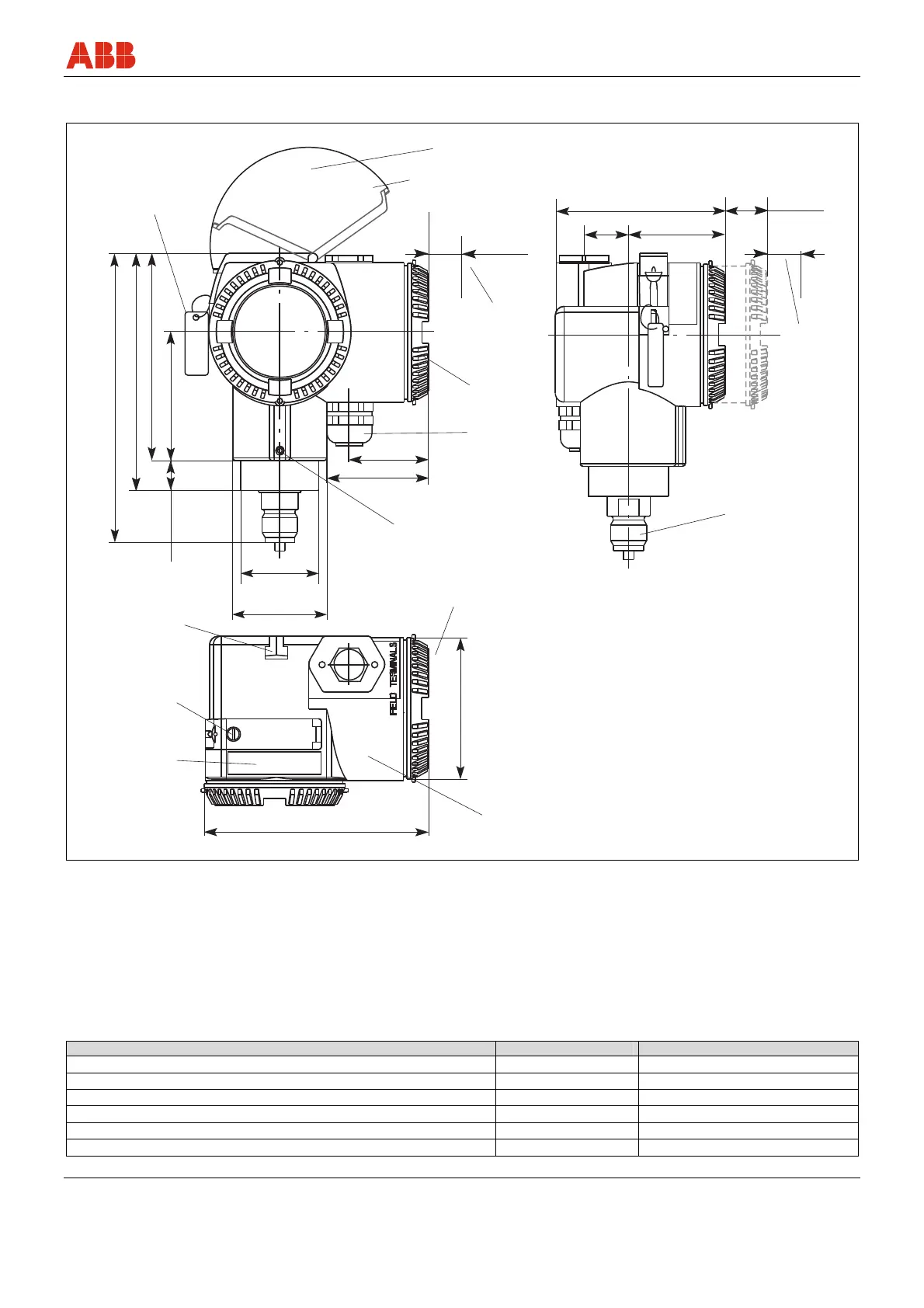
9.9.2 Pressure transmitter with DIN housing
1
2
3
4
5
6
7
8
9
10
12
70(2.76)
M00046
47(1.85)
56(2.20)
76(2.99)
124(4.88)
A
~48(1.89)
~61(2.40)
~130(5.12)
26
(1.02)
~58(2.28)
~100(3.94)
~136(5.35)/*~140(5.51)
83(3.27)
Ø
*28(*1.10)
12(0.47)
*16(0.63)
23(0.91)
20(0.79)
11
20(0.79)
11
Fig. 25: Dimensions in mm (inch)
1 Tag for indicating measuring points, for example (optional)
2 Groove for screws (wall or pipe mounting)
3 Captive fixing screw for keyboard cover
4 Plate with button legend, etc.
5 Name plate
6 Terminal side
7 Housing stop screw
8 Electrical connection
9 Housing cover
10 Space required for rotating the keyboard cover
11 Space for removing the cover required
12 Process connection
* Dimensions for sensor code L, D, U, R, V
Dimension "A" is dependent on the measuring range and process connection.
Process connection Sensor code C, F Sensor code L, D, U, R, V
½ -14 NPT male thread 168 (6.61) 173 (6.81)
½ -14 NPT female thread 158 (6.22) 169 (6.65) 172 (6.77) – Sensor V
DIN EN 837-1 G ½ B spigot 167 (6.58) 173 (6.81)
DIN EN 837-1 G ½ B (HP) spigot for connections with convex seal 178 (7.01) 183 (7.20)
Flush diaphragm - See pages that follow
For installation in ball valve - See pages that follow