Commissioning
IM/265Gx/Ax-EN-07 265Gx, 265Ax 41
6.4 Turning the housing in relation to the measuring equipment
The electronics housing can be rotated 360° and fixed in any position; a stop is provided to
prevent it from rotating past this point.
• To activate this, slacken the housing stop screw on the neck of the housing (hex-head
socket screw SW 2.5) by approx. 1 rotation (do not pull it out) and, once the desired position
has been reached, retighten it until hand-tight.
6.5 Installing / Removing the button unit
1. Slacken the screw on the protective cap and move the cap to one side.
2. Using a suitable screwdriver, for example, push the lock bar all the way out of the button
unit.
3. This releases the square nut; remove this from the button unit.
4. Use a Torx screwdriver (size T10) to slacken the fixing screw for the button unit, and then
remove the unit from the electronics housing.
5. If necessary, insert a filler piece and secure it using the screw supplied.
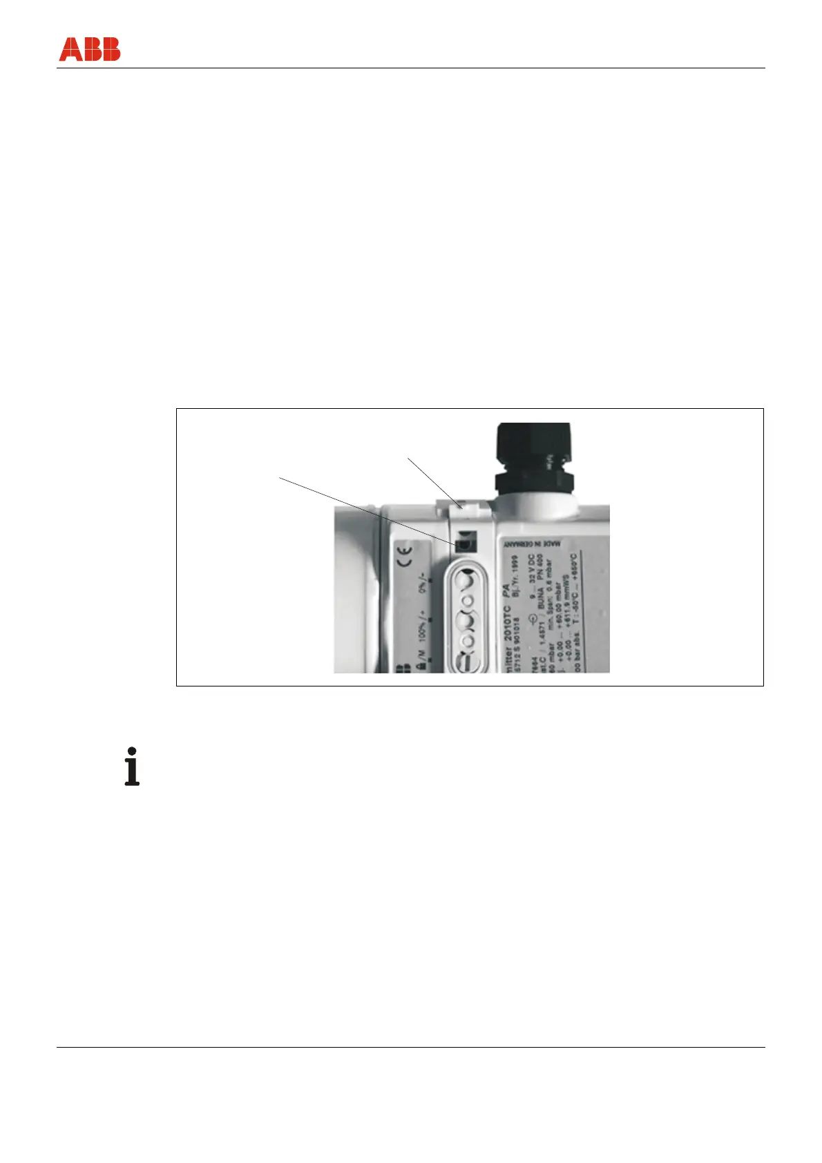
M00042
1
2
Fig. 14: Installing/removing the button unit
1 Fixing screw 2 Lock bar
IMPORTANT (NOTE)
The fixing screw is located underneath the button unit.