Specifications
76 265Gx, 265Ax IM/265Gx/Ax-EN-07
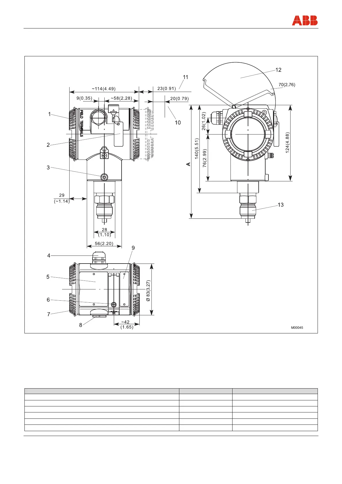
9.9 Mounting dimensions (not design data)
9.9.1 Pressure transmitter with barrel housing
Fig. 24: Dimensions in mm (inch)
1 Terminal side
2 Tag for indicating measuring points, for example (optional)
3 Housing stop screw
4 Electrical connection
5 Name plate
6 Captive fixing screw for keyboard cover
7 Housing cover
8 Electrical connection (with blind plug)
9 Plate with button legend, etc.
10 Space required for removing the cover
11 With LCD indicator
12 Space required for rotating the keyboard cover
13 Process connection
Dimension "A" is dependent on the measuring range and process connection.
Process connection Sensor code C, F Sensor code L, D, U, R, V
½ -14 NPT male thread 168 (6.61) 173 (6.81)
½ -14 NPT female thread 158 (6.22) 169 (6.65) 172 (6.77) – Sensor V
DIN EN 837-1 G ½ B spigot 167 (6.58) 173 (6.81)
DIN EN 837-1 G ½ B (HP) spigot for connections with convex seal 178 (7.01) 183 (7.20)
Flush diaphragm - See pages that follow
For installation in ball valve - See pages that follow