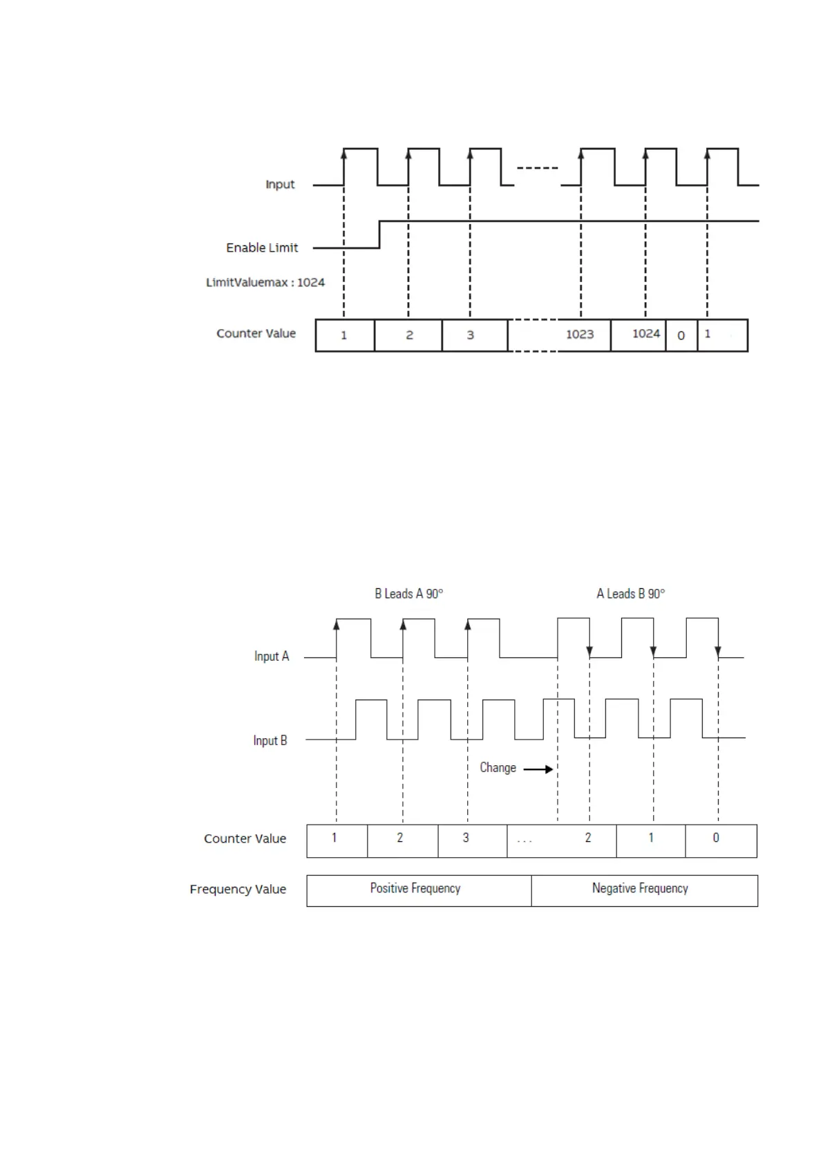
After “CounterValue” reaches the “LimitValueMax”, the “OBIOEncoderCounter” instruction writes
0 to the “CounterValue”.
“Encoder Counter Mode”: 0 = “90° Mode”.
In this encoder counter mode, an increasing count results when input B is 90° ahead of input A.
The count is initiated on the rising edge of input A, and the direction of the encoder is clockwise
(positive).
The module produces a decreasing count when input A is 90° ahead of Input B.
The count is initiated on the falling edge of input A, and the direction is counterclockwise (nega-
tive).
By monitoring both the number of pulses and the phase relationships of input A and B, you can
accurately determine the position and direction of the rotation.
“Encoder Counter Mode”: 1 = “Pulse/Direction”.
In this encoder counter mode, the count increases or decreases based on the state of input B,
which can be a random signal.
If input B is high, the counter will count down.
If input B is low the counter counts up.
Counting is done on the leading edge of input A.
System technology > Use the onboard I/Os as encoder with A and B signals
2021/06/29 3ADR010635, 2, en_US 175
 Loading...


