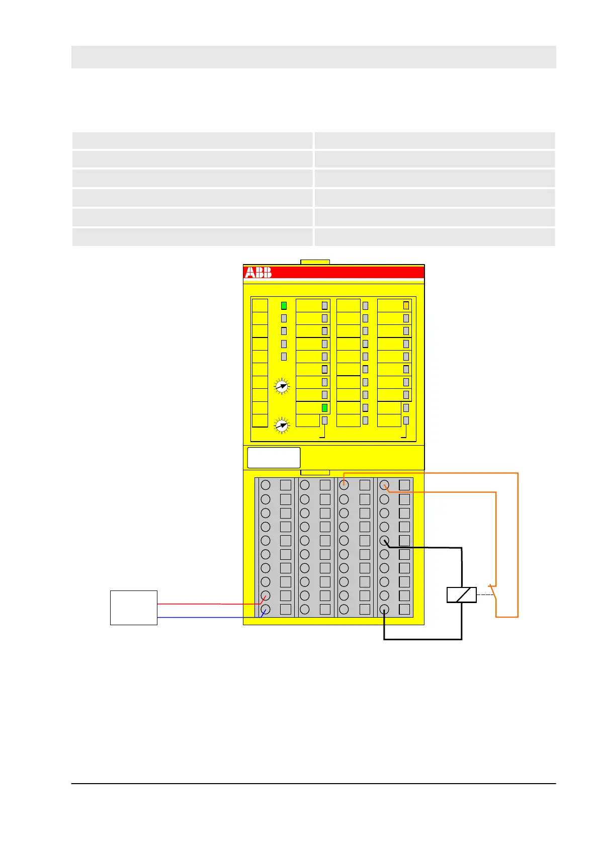
Relay
Sensor power supply on channel 1 (I4) Internal using test pulse T2
Internal output channel test Yes
SIL/Cat./PL
1)
SIL 1/Cat.1/PL c
SIL
2)
SIL 2
SIL/Cat./PL
3)
SIL 2/Cat.2/PL d
SIL
4)
SIL 3
1.0
1.1
1.2
1.3
1.4
1.5
1.6
1.7
1.8
1.9
2.0
2.1
2.2
2.3
2.4
2.5
2.6
2.7
2.8
2.9
3.0
3.1
3.2
3.3
3.4
3.5
3.6
3.7
3.8
3.9
4.0
4.1
4.2
4.3
4.4
4.5
4.6
4.7
4.8
4.9
DX581-S
3.8
UP
3.9
ZP
3.7
3.0
T2
3.1
3.2
T3
3.3
3.5
3.4
3.6
UP 24VDC 100W
8SDI 8SDO
Safety Digital Input 24VDC
Safety Digital Output 24VDC 0.5A
ERR2
4.9
ZP
4.2I6
4.0
I4
4.1
I5
4.3
I7
4.4
O4
4.5
O5
4.6O6
4.7
O7
4.8
UP
ERR1
2.9
ZP
2.2I2
2.0
I0
2.1
I1
2.3
I3
2.4
O0
2.5
O1
2.6O2
2.7
O3
2.8
UP
PWR
1.9
ZP
1.8
UP
1.7
1.0
T0
1.2
T1
1.3
1.1
1.5
1.4
1.6
ADDR
x10H
ADDR
x01H
GND
24 VDC
Readback contact
(with or without)
K1
C
4
3
B
2
A
1
9
0
8
F
7
E
6
D
5
C
4
3
B
2
A
1
9
0
8
F
7
E
6
D
5
Fig. 44: Circuit example DX581-S, Relay
1)
- Without readback contact: Max reachable (ISO 13849, IEC 62061, EN 954) ➔ without error exclusion
(you can reach higher levels up to PL e, SIL 3, Cat. 4, with error exclusion) MTTFd = High; DC = 0
2)
- Without readback contact: Max reachable SIL acc. IEC 61508 (Typ A components are required) ➔
without error exclusion (you can reach higher level up to SIL3 with error exclusion)
AC500-S Safety Modules
DX581-S digital safety input/output module > Circuit examples
30.03.2017 AC500-S 119