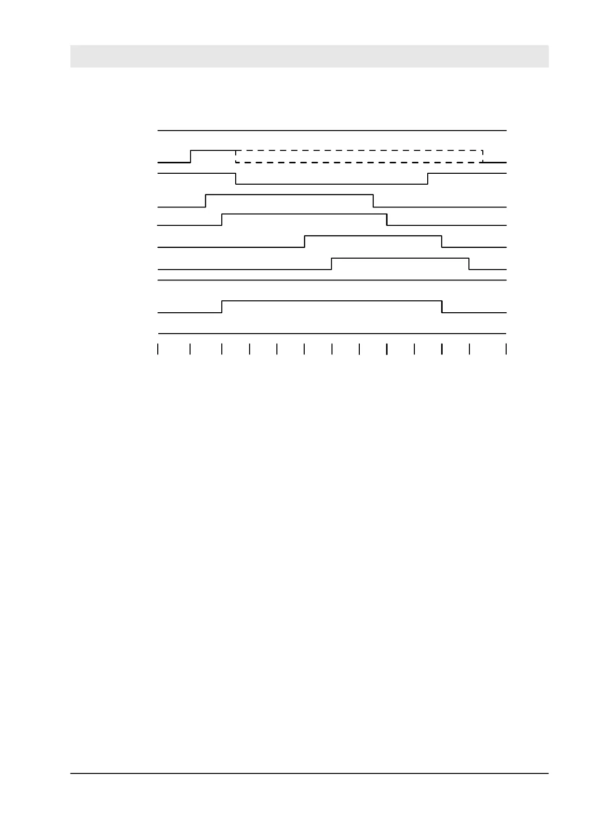
Typical Timing Diagram
Activate
MutingEnable
S_AOPD_Out
MutingSwitch11
MutingSwitch12
MutingSwitch21
MutingSwitch22
S_AOPD_In
S_MutingAcitve
DiagCode
Error
8000 8000/8011 8012 8012 8012 8014 8021 8021
8021
8021
8000
8000
Fig. 115: Timing diagram for SF_MutingPar
The FB detects the following error conditions:
n DiscTime11_12 and DiscTime21_22 have been set to values less than T#0s or greater than T#4s.
n MaxMutingTime has been set to a value less than T#0s or greater than T#10min.
n The discrepancy time for the MutingSwitch11/MutingSwitch12 or MutingSwitch21/MutingSwitch22 sensor
pairs has been exceeded.
n The muting function (S_MutingActive = TRUE) exceeds the maximum muting time MaxMutingTime.
n Muting sensors MutingSwitch11, MutingSwitch12, MutingSwitch21, and MutingSwitch22 are activated in
the wrong order.
n Muting sequence starts without being enabled by MutingEnable
n A faulty muting lamp is indicated by S_MutingLamp = FALSE.
n A static Reset condition is detected in state 8001 and 8003.
Error Behavior
In the event of an error, the S_AOPD_Out and S_MutingActive outputs are set to FALSE. The DiagCode
output indicates the relevant error code and the Error output is set to TRUE.
A restart is inhibited until the error conditions are cleared and the Safe state is acknowledged with Reset by
the operator.
Configuration and programming
AC500-S Libraries > SafetyBlocks_PLCopen_AC500_v22.lib
30.03.2017 AC500-S 351
 Loading...


