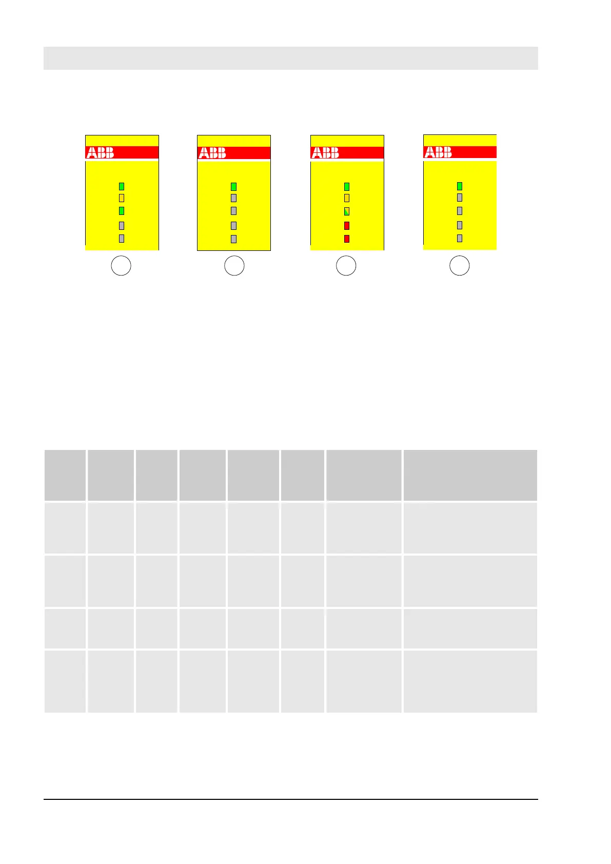
The next figure shows LED states of SM560-S Safety CPU, which can be observed during its start-up.
SM560-S
DIAG
PWR
RUN
I-ERR
E-ERR
SM560-S
DIAG
PWR
RUN
I-ERR
E-ERR
SM560-S
DIAG
PWR
RUN
I-ERR
E-ERR
SM560-S
DIAG
PWR
RUN
I-ERR
E-ERR
1
2
43
Fig. 10: LED states of SM560-S Safety CPU during start-up
1 State 1 – Hardware reset
2 State 2 – Initialisation
3 State 3 – LED test
4 State 4 – End of start-up
SM560-S error messages are aggregated together with other communication module error messages in
SM560-S and PM5xx CPUs. Following Table includes a list of error messages related to SM560-S Safety
CPU (all of them can be observed on PM5xx using, e.g., “diagshow all” PLC browser command).
Table 4: List of error messages for SM560-S
Error
class
Compo-
nent or
Inter-
face
Device Module Channel Error Error text Remedy
E2 1 … 4 255 30 1 2 Internal PRO-
FIsafe initiali-
zation error
Restart Safety PLC. If this
error persists, replace
Safety PLC. Contact ABB
technical support.
E2 1 … 4 255 30 2 2 Internal PRO-
FIsafe error
Restart Safety PLC. If this
error persists, replace
Safety PLC. Contact ABB
technical support.
E2 1 … 4 255 30 3 30 PROFIsafe
configuration
error
Check F-Parameter config-
uration of I/O module and
reload boot project.
E2 1 or 9 1 … 4 1 0 17 Access test
failed
For Safety PLC: Check
Safety PLC switch address
setting. Restart Safety PLC.
If this error persists, replace
Safety PLC.
AC500-S Safety Modules
SM560-S Safety CPU > Diagnosis and LED status display
30.03.2017AC500-S42