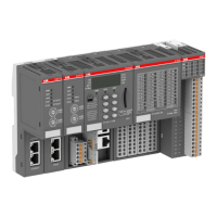
Fig. 12: AC500, equipotential bonding
1 Cabinet 1
2 Cabinet 2
3 Power supply for the CPU
4 Fuse for the CPU power
5 Power supply for the I/Os
6 Fuse for the I/O power
7 For fuses for the contacts of the relay outputs
8 0V rail
9 Grounding of the 0V rail
10 Cabinet grounding
11
Equipotential bonding between the cabinets min. 16 mm
2
12 Cable shields grounding
13 Fieldbus connection (e.g. Ethernet)
6.3 Connection and wiring
This chapter provides general information about the platform.
Specific information about the connections of the modules and the wiring is available in the
installation instructions.
● Installation instructions of AC500 PLC product family
● Installation instructions of CP600 control panels
2023/03/03 3ADR011074, 1, en_US 63

 Loading...