Connecting the power cables – IEC (shielded cables)
■
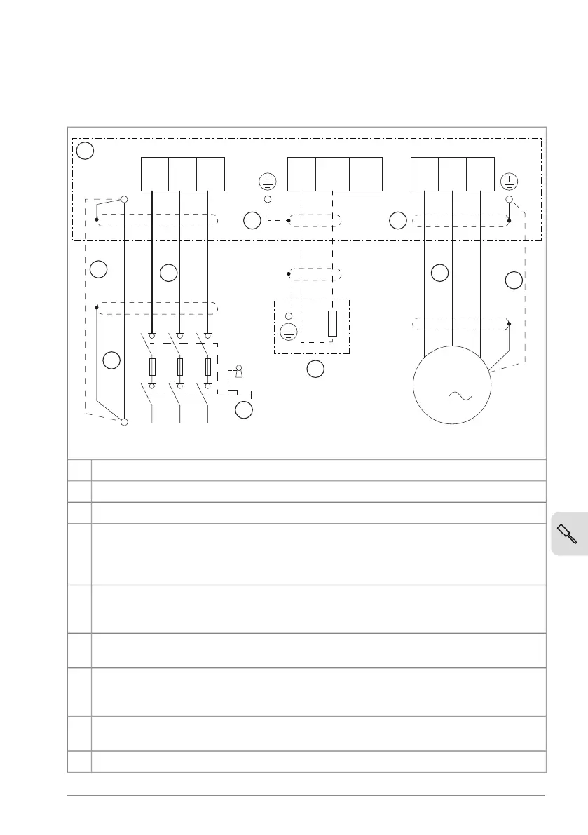
Connection diagram
PE
PE
L1 L2 L3
R-
R+
UDC+
UDC-
U1 W1
M
PE
3
T1/
U
T2/
V
T3/
W
V1
2
3
4
5
6
7
8
9
8
L1 L2 L3
(L) (N)
1
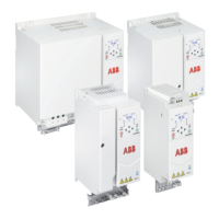
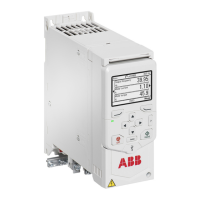
Drive1
Disconnecting device2
Input power cable3
Two protective earth (ground) conductors. Drive safety standard IEC/EN 61800-5-1
requires two PE conductors for a fixed connection, if the cross-section of grounding
conductor is less than 10 mm
2
Cu or 16 mm
2
Al. For example, you can use the cable
shield in addition to the fourth conductor.
4
Separate PE cable (line side). Use a separate grounding cable or a cable with a separate
PE conductor for the line side, if the conductivity of the fourth conductor or shield
does not meet the requirements for the PE conductor.
5
Motor cable. ABB recommends to use a symmetrical shielded cable (VFD cable) as
motor cable.
6
Separate PE cable (motor side). Use a separate grounding cable for the motor side, if
the conductivity of the shield is not sufficient, or if there is no symmetrically constructed
PE conductor in the cable.
7
360° grounding of the cable shield. Required for the motor cable and brake resistor
cable (if used).
8
Brake resistor (optional, for frames R2...R4 only).9
Electrical installation 67


 To Next Page