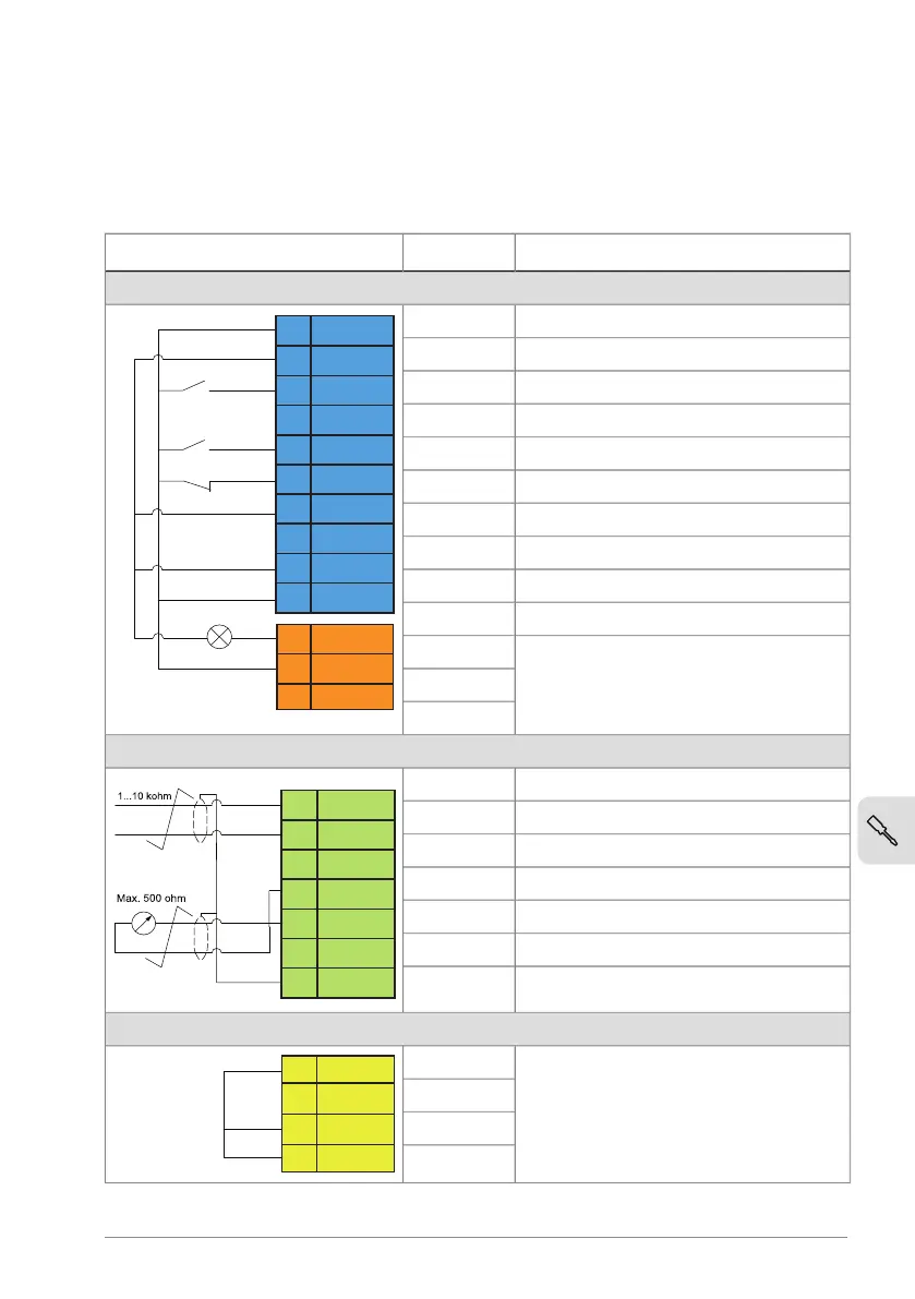
Connecting the control cables
See below for the default I/O connection diagram (HVAC default).
■
Default I/O connection diagram (HVAC default)
DescriptionTerm.
2)
Connection
Digital I/O and relay output connections
Aux. +24 V DC, max 200 mA24 V
21
22
8
9
10
11
12
18
19
20
5
6
7
24V
DGND
DI1
DI2
DI3
DI4
DCOM
DO
DO SRC
NC
COM
NO
DO COM
Aux. voltage output commonDGND
Stop (0) / Start (1)DI1
Not configuredDI2
Constant speed selectionDI3
Start interlock 1 (1 = allow start)DI4
Digital input commonDCOM
Not energizedDO
Digital output commonDO COM
Digital output auxiliary voltageDO SRC
Damper controlNC
COM
NO
Analog I/O
Speed reference (0…10V)AI1/DI5
AI1/DI5
AGND
AI2
AGND
AO
10V
SCREEN
14
13
15
16
17
23
24
1)
1)
Analog input circuit commonDGND
Not usedAI2
Analog output circuit commonAGND
Output frequency (0...20mA)AO
Ref. voltage +10 V DC10V
Signal cable shield (screen)SCREEN
Safe torque off (STO) (only on ACH180-04S)
Safe torque off function.S+
Connected at the factory. Drive starts
only when both circuits are closed.
SGND
S1
S2
Electrical installation 73