■
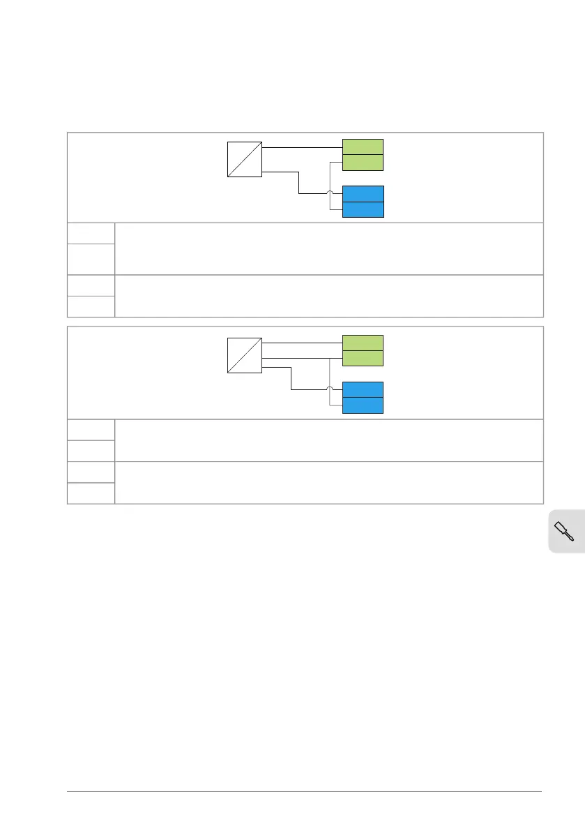
Connection examples of two-wire and three-wire sensors
The figures give examples of connections for a two-wire or three-wire
sensor/transmitter that is supplied by the auxiliary voltage output of the drive.
P
I
-
+
4…20 mA
AI2
AGND
+24V
DGND
Process actual value measurement or reference, 4 … 20 mA, R
in
= 205 ohm.
Note: The sensor power supply comes through its current output circuit, use
4 … 20 mA signal, not 0 … 20 mA.
AI2
AGND
Auxiliary voltage output, non-isolated, +24 V DC, max. 100 mA+24V
DGND
Process actual value measurement or reference, 0(4)…20 mA, R
in
= 205 ohmAI2
AGND
Auxiliary voltage output, non-isolated, +24 V DC, max. 100 mA+24V
DGND
■
Safe torque off
For the drive to start, both STO connections must be closed. By default, the terminal
block has jumpers to close the circuit. Remove the jumpers before connecting
external Safe torque off circuitry to the drive. See chapter The Safe torque off
function.
Connecting a PC
To connect a PC to the drive, there are two alternatives:
• Use an ACH-AP-H/W assistant control panel as a converter. Use a USB type A
– type Mini-B cable. The maximum permitted length of the cable is 3 m (9.8 ft).
• Use a USB to RJ45 converter. You can order it from ABB (BCBL-01,
3AXD50000032449). Connect the cable to the Panel and PC tool port (RJ45).
Electrical installation 79
 Loading...