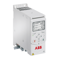
8. If you use a brake resistor, connect the brake resistor cable to the R- and UDC+
terminals. Use shielded cable and ground the shield under the grounding clamp
(360-degree grounding).
9. Strip the input power cable.
10. If the input power cable has a shield, ground the shield under the clamp (360-degree
grounding). Twist the shield also into a bundle, mark it with yellow-green insulation
tape, fit a cable lug, and connect it to the grounding terminal.
11. Connect the PE conductors of the input power cable to the grounding terminal.
12. Connect the phase conductors of the input power cable to the L1, L2 and L3 input
terminals.
13. Mechanically attach all of the cables on the outside of the drive.
Electrical installation – IEC 71

 Loading...